


Shallow-Depth Theory
As shown in the figure, in a sedimentation tank with a pool length of L, a pool depth of H, a horizontal flow velocity of v in the pool, and a particle settling velocity of u0, under ideal conditions, L/H equals v/u0.
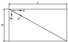
Sedimentation Tank Schematic
If the flow rate is V, the area of the sedimentation pond bottom is A, and the sedimentation time is t, then
V = H·A/t, t = L/v = H/u0, hence
V=A u0
Clearly, the treatment capacity of the sedimentation pond is only related to the bottom area A and the settling velocity u0, and not to the depth of the sedimentation pond.
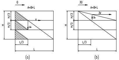
If horizontal partitions are used, the H is divided into 3 layers, each with a depth of H/3, as shown in Figure (a). Under the condition that u0 and v remain constant, only L/3 is needed to remove particles with settling velocity u0, thereby reducing the total volume to 1/3. If the pool length L remains unchanged, as shown in Figure (b), due to the pool depth being H/3, the horizontal velocity can be increased to 3v, still allowing particles with settling velocity u0 to settle out, thus increasing the processing capacity by a factor of 3.
Dividing the sedimentation tank into n layers can increase the treatment capacity by a factor of n. This is the theory of shallow pond sedimentation.
To address the sludge discharge issue in sedimentation basins, in practical applications of the shallow pond theory, horizontal baffles are replaced with inclined plates at an angle α, which is set at 50° to 60°. Therefore, the total effective area of the inclined plates, multiplied by cosα, yields the horizontal sedimentation area.
n
A=∑A 1 cosα
1
By the equation V = A * u0, if the sedimentation efficiency and u0 remain constant, the area A of the sedimentation zone increases by n times, theoretically the water volume passing through can also increase by n times. The inclined plate sedimentation tank utilizes many inclined plates to increase the sedimentation area A, forming numerous shallow sedimentation ponds, thereby significantly enhancing the treatment capacity of the inclined plate sedimentation tank.
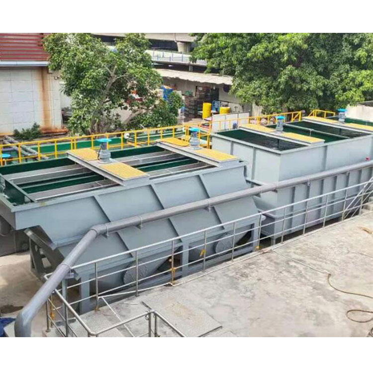
Operating Principle
Wastewater enters the pool through the inlet pipe, flows downward through the inlet chamber located in the middle of the pool, is reflected by the weir plates, and then enters the inclined plate through the internal water distribution orifice.
As the solution flows upward, the contained solid particles settle on the parallel inclined plate components, then slide into the sludge pit at the bottom of the pool. In the sludge pit, the sludge is concentrated and discharged through the sludge outlet. The clarified liquid leaves the inclined plates through the outlet holes at the top and then flows together through adjustable overflow weirs, exiting via the outlet pipe.
The purpose of designing passage holes at the top of the inclined plate is to create a pressure difference as the clarified liquid flows through the collecting channel, ensuring uniform flow distribution between the plates and utilizing the entire surface area. This operation enhances reliability, reduces the impact of fluid flow, and also minimizes the possibility of scaling and sedimentation.

Principle Diagram
Features
(1) Increase precipitation capacity:
a) Increased sedimentation area;
b) The inclined plate can re-agglomerate the sediment, causing the flocs to increase in size and making them easier to settle.
c) Slant board sedimentation creates laminar flow conditions, resulting in excellent sedimentation performance.
(2) Treated sludge concentration increases.
(3) The discharged clean water volume remains stable throughout the year, and there is no sludge coverage.
Application Range
Lamella separators are primarily used for tapping into the potential or expanding the treatment capacity of existing wastewater treatment plants, and as a primary sedimentation tank when the plant is constrained by limited land area. Specific applications include:
Metalworking wastewater treatment
(2) CPI process treatment and wastewater treatment
Surface Water Purification
(4) Factory Sludge Washwater Treatment
(5) Low-capacity wastewater treatment at the factory
(6) Municipal Phosphate Wastewater Treatment
(7) Pulp Reclaiming Wastewater Treatment
Composition
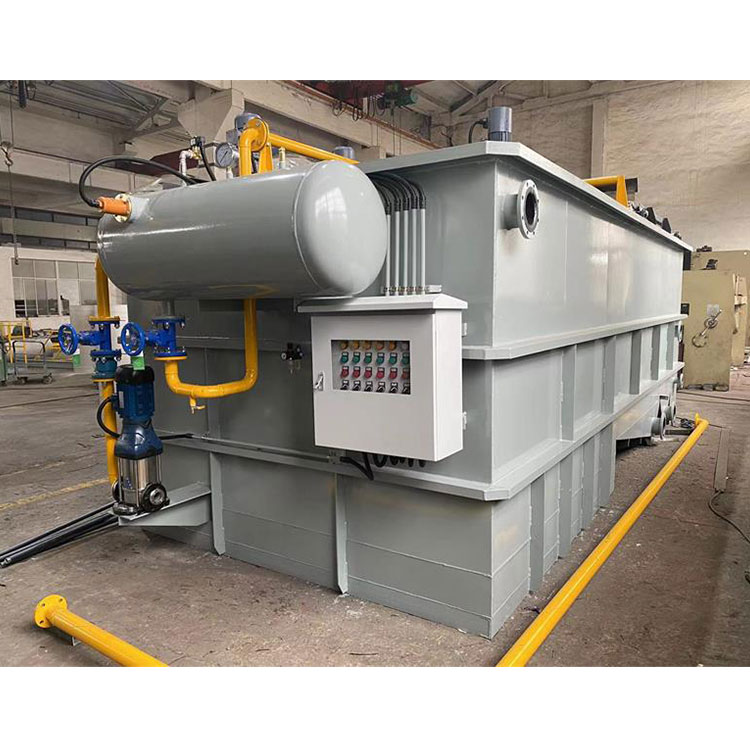
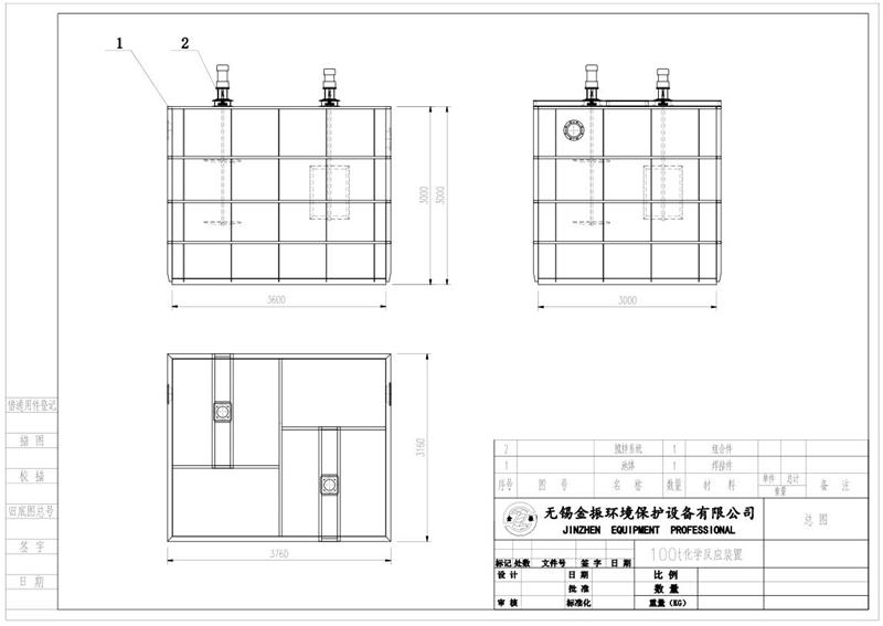
The lamella separator, designed for various application scenarios and to handle wastewater with high sludge content, is engineered to maximize dry sludge volume. The design integrates the sludge sedimentation and concentration sections and includes a scraper. The structural diagram is as shown below.
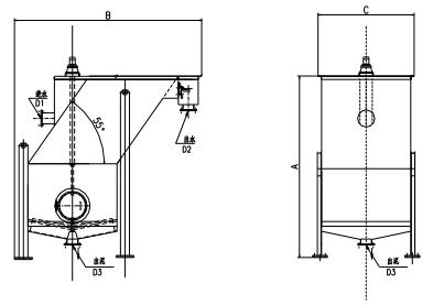
Illustration
Its application range is: large design flow rate of 300 m3/h, sedimentation area of 15 to 190 m2, and base area of 1.8×3.0 m to 3.2×4.4 m.
A flocculation pond can be installed before the water enters, which, through the action of flocculants, makes the wastewater and sludge entering the inclined plate sedimentation pond easier to settle, resulting in better treatment effects.
Inclined plate component, which can be installed in existing sedimentation basins to enhance their treatment capacity. Multiple sets of inclined plate components can also be used together. The structural diagram is as shown below.
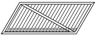
Illustration of inclined plate component
The complete set of equipment includes: housing, inlet trough, sludge scraper, weir component, distributor plate, collecting trough, outlet trough, etc.
Technical Specifications
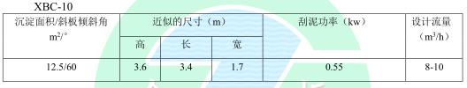
JFY100 Chemical Reaction Equipment (1) - Model

JXBC100 LAMIRA Sedimentation Tank (1) - Model