


Overview and Usage:
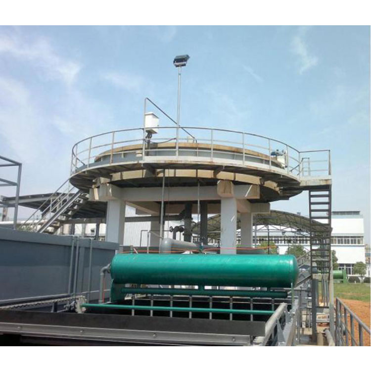
In the water supply and drainage treatment process, solid-liquid separation technology and its equipment are one of the key projects. Air flotation is one of the highly effective methods for removing fine suspended particles with a specific gravity close to that of water.
The equipment is widely used in water supply and drainage treatment projects. One, it is applied in water purification plants using lake water as a source for algae removal and turbidity reduction; two, it is used in industrial wastewater treatment projects, such as in the petrochemical, textile, dyeing and printing, electroplating, leather, and food industries; three, it is applied in the recovery of useful substances from wastewater, such as fiber recovery from papermaking and pulp water.
Model Features

Features
Effective water depth: 400-500mm
2. Hydraulic Retention Time in the Pool (3-5 mins).
3. High purification volume, meaning high surface load.
4. Small land area, light unit load, all pre-fabricated components assembled, no operation room required, equipment can be suspended or multi-layered combined.
Low installation and maintenance costs, easy to clean.
High purification level, with a suspended solids removal rate exceeding 90%.
7. The unit employs a JFA-type aeration system, which boasts a clever design and an aeration efficiency of up to 90%, with a volume just one-fifth of a typical aeration system.
Main Working Principle of the Product
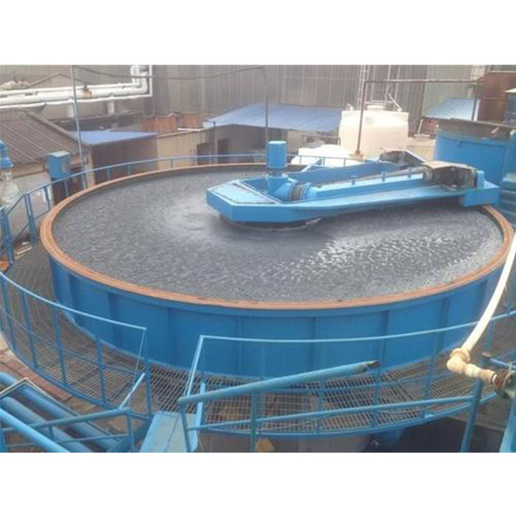
The air flotation separation technology refers to the process where air is dissolved into water to the maximum extent under certain pressure conditions, aiming for a saturated state. Then, the pressure-soluble air water is released through pressure reduction, generating a large number of fine bubbles. These bubbles thoroughly contact the suspended flocs in the water, causing the flocs to adhere to the microbubbles. As the bubbles rise to the surface along with the flocs, they form a floating scum, which is then scraped off to purify the water quality.
Our company has developed the JQF type shallow gas flotation device, which is a rapid gas flotation system. It successfully applies "shallow layer theory" and "zero speed" principles on top of traditional gas flotation theory. Through careful design, it integrates coagulation, gas flotation, skimming, sedimentation, and sludge scraping into one, making it a water purification and treatment equipment.
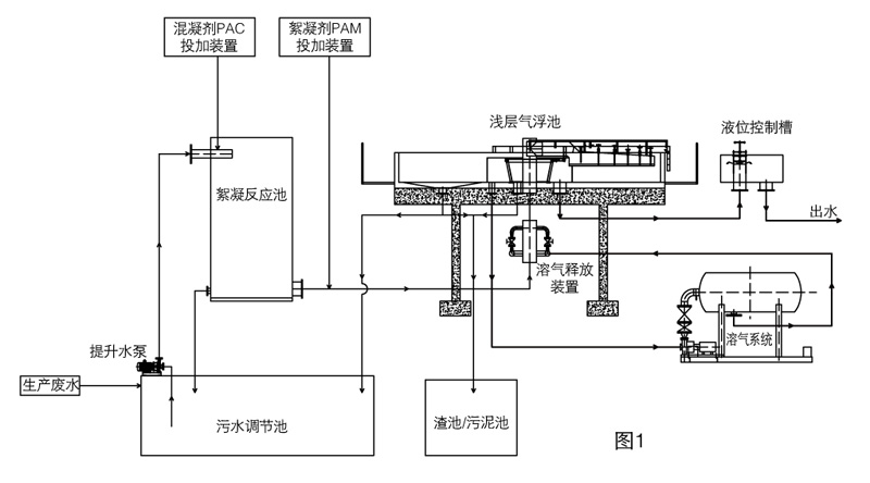
Process Flow
Parameters and Specifications
Key Technical Parameters
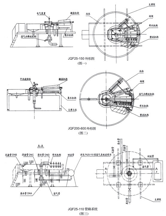
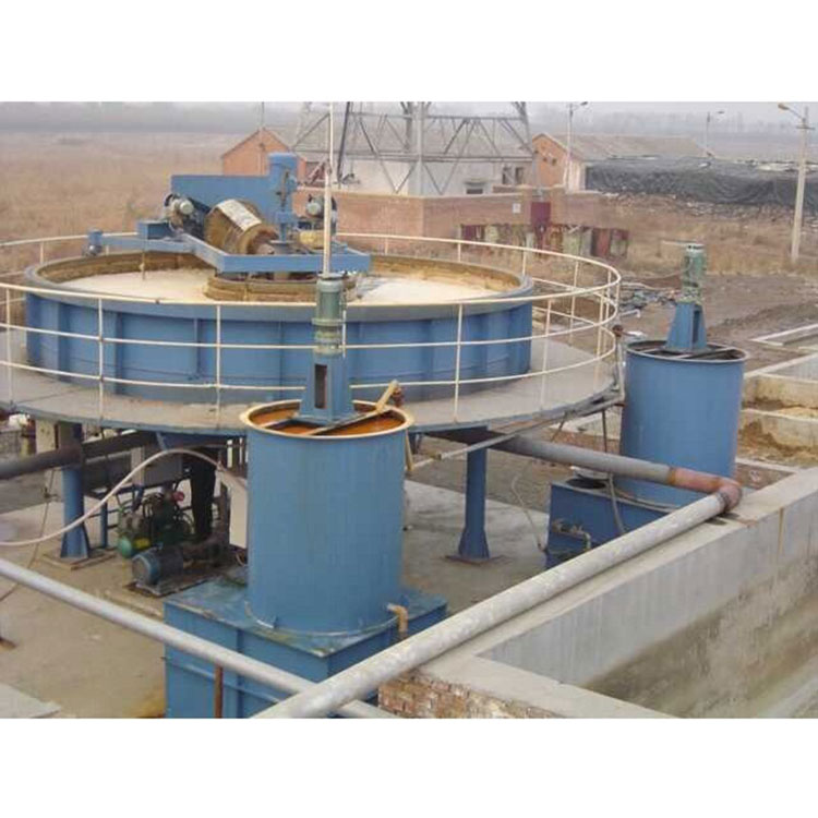
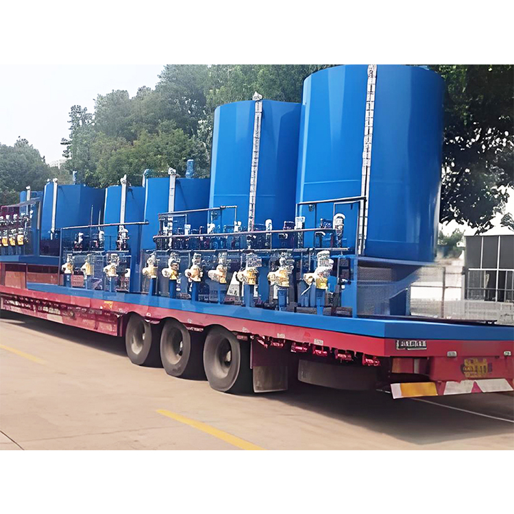
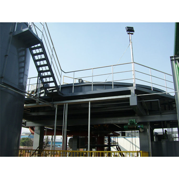
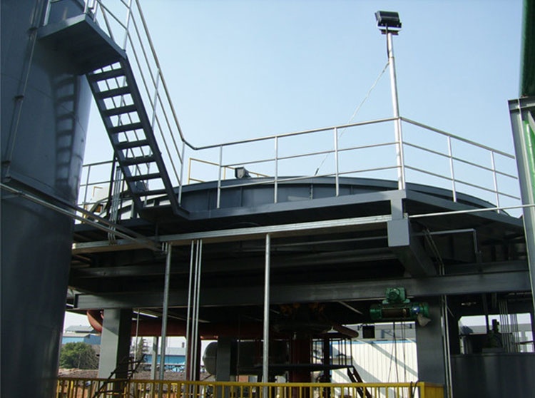
The JQF type shallow flotation device integrates coagulation, air flotation, skimming, sedimentation, and sludge scraping into one, with a compact cylindrical structure and a relatively shallow pool. The main body of the device consists of five main parts: the pool body, a rotating water distribution mechanism, an aeration release mechanism, a framework mechanism, and a water collection mechanism. The inlet, outlet, and sludge排出口 are all concentrated in the central area of the pool body. The water distribution mechanism, water collection mechanism, and aeration release mechanism are all tightly connected to the framework and rotate around the center of the pool body.
This unit provides a complete set of equipment assemblies and control systems, combining centralized and decentralized control to achieve optimal equipment operation (refer to Figures 1 and 2 for details).

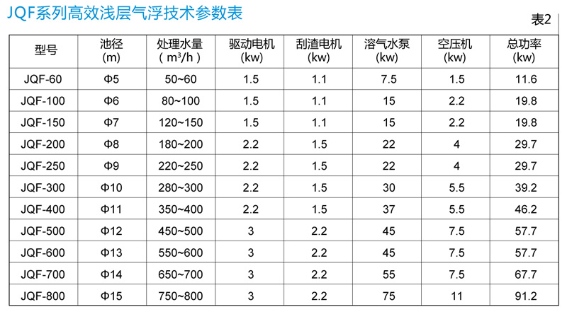
Note: 1. The water treatment capacity in the table is based on a recycle ratio R=30% and hydraulic surface load: q=6-8 m³/m².h. 3. JQF25-JQF200 refers to steel pool bodies, with the working load indicating the total load the civil foundation bears during normal operation of the entire unit.
JQF200-JQF600 is for civil construction pools, and its working load refers to the total load the concrete pool body withstands during normal operation of the entire unit.
JQF200 has a working load of 45/37 (t), where 45t refers to the total load carried by the civil foundation when the tank body is made of steel. 37t refers to the total load carried by the concrete tank body when the tank body is made of concrete.
Table 3: JQF25-110 Pipeline Parameters (Refer to Figure 3)
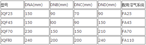
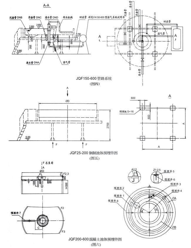
Table 4: JQF150-JQF600 Pipeline Parameters (see Figure 4)

Table 5: JQF25-200 Steel Pool Body Embedment Parameters (see Figure 5)

Table 6: JQF200-600 Concrete Tank Insert Parameters (See Figure 6)