


Installation Precautions for Stainless Steel Spiral Hoist:
1. The foundation must be poured and completed 20 days prior to the formal installation of the stainless steel helical elevator, ensuring it reliably supports the equipment and prevents sinking or additional deformation of the helical elevator due to insufficient ground support, guaranteeing sufficient stability during operation.
2. Prior to installation, all components that have accumulated dust and grime during transit or unboxing must be cleaned.
3. The vertical and horizontal tolerances for the stainless steel helical lift machine housing and the main frame at both ends are one thousandth of the length.
4. The bearing surfaces of the covers on all shells of the stainless steel helical hoist should be in the same plane along the full length of the helical machine.
5. The adjacent inner surfaces of the adjacent stainless steel spiral lifters must not have significant heights at their joint areas.
6. After the shell is properly mounted, all bases of the stainless steel spiral lifting jack should be securely seated before tightening the foot bolts.
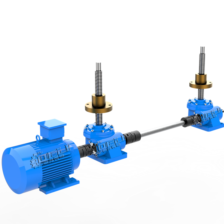
7. The intermediate suspension bearings of the stainless steel helical lift should reliably support the connecting shaft between the two helical sections, without causing the helix to be jammed or bent. During installation, an adjustment washer can be added between the base of the suspension bearing and the machine housing support angle iron to ensure that all suspension bearings are concentric.

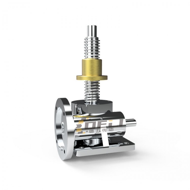
Stainless Steel SpiralThe outer diameter of the elevator and the small gap at the bottom of the semi-circular groove on the housing must not be less than the nominal gap during installation.70%;
The clearance between the end face of the roller bearing in the end flat bearing assembly and the end face of the bearing housing and end cover must not be less than 2mm.
2. To adjust the cumulative deviation between the casing and screw length, the screw machine allows for the addition of asbestos strips between the casings during installation. For higher sealing requirements, waterproof coarse canvas can also be used as a pad between the casing and the cover.
3. The drive unit's final speed shaft and screw conveyor should be concentric. If the drive unit uses a balanced coupling to connect with the screw conveyor's drive shaft, the parallelism deviation between the drive unit's final speed shaft and the screw conveyor's drive shaft must not exceed 1/100, and the parallel displacement of the axes must not exceed 0.2 mm.
All connecting screws should be tightened to a reliable degree.
5. On-site installation of the in and out material ports should ensure that the flange support surface of the material ports is parallel to the axis of the stainless steel helical lifting machine and tightly fits the connected flange; no gaps are allowed.