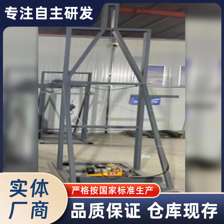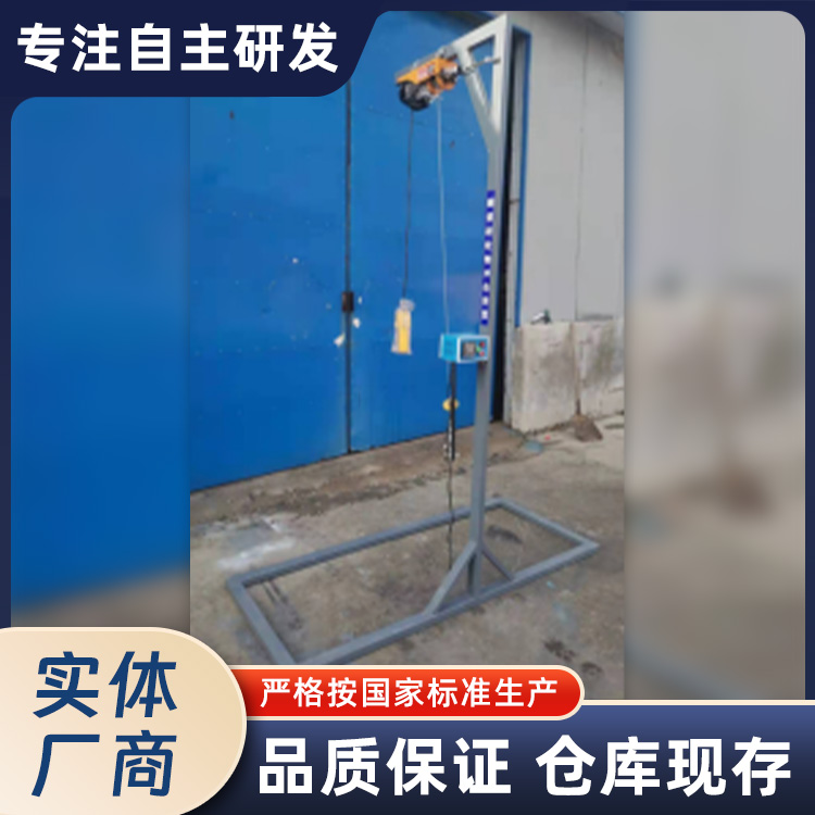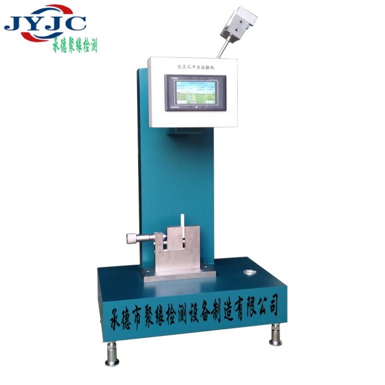


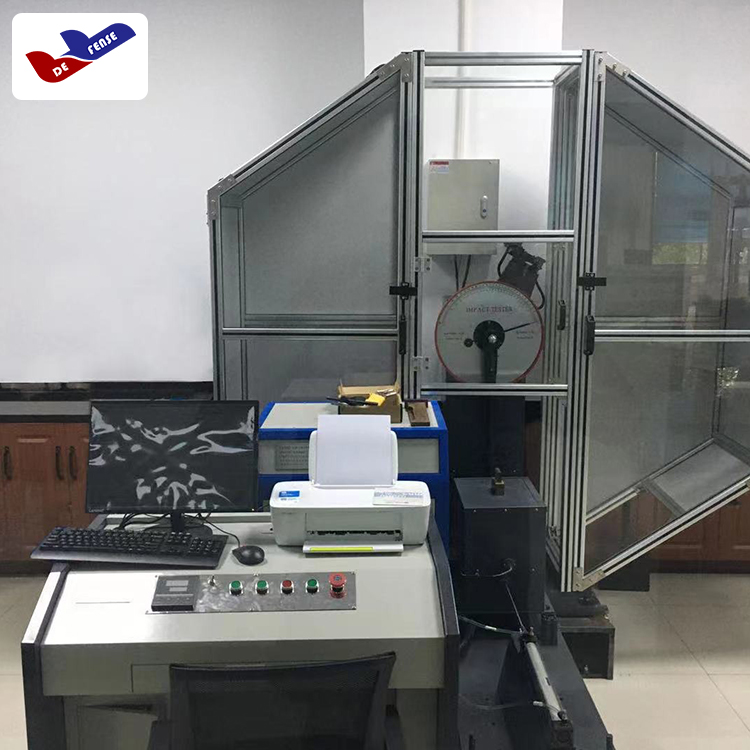


This series of digital impact testing machines is mainly used for measuring the impact toughness of non-metallic materials such as hard plastics, reinforced nylon, fiberglass, ceramics, cast stones, and electrical insulation materials. It is an ideal testing equipment for the chemical industry, research institutions, colleges, quality inspection and other departments.
feature:
1This series of impact testing machines adopts DeltaPLCIntelligent digital impact testing machine developed and produced using microcomputer technology. The advanced feature is that it can automatically correct the energy loss caused by friction and wind resistance, eliminating the need for numerical charts that correct energy due to the influence of resistance. The detection of residual energy and correction of energy loss of the pendulum after sample fracture is completed in one go during the impact process.
2This series of impact testing machines all use DeltaPLCMicrocomputer control, 5-inch touch screenThe display operation shows the test results, making the reading more intuitive. Using high-precision split type photoelectric encoder to test accuracy, the angle accuracy reaches0.04The accuracy and precision of the impact machine have been improved, avoiding the trouble of frequent replacement of the pendulum on the dial display. The power supply adopts the original power supply of Mingwei Company to ensure stable power supply during operation.
XJJCThe main technical parameters of the series of simply supported beam impact testing machines fully comply withIS0 179、GB/T 1043、JB/T 8762 Regulations of Standard Huai
Technical Specifications:
1、 Main technical indicators

2Operating temperature: 15 ℃ -35 ℃
3Electricity Source:AC220V 、50Hz
4Digital display indication value:5Jbelow0.001J(Including)5J);5Jabove0.01J
5The numerical display impact machine has the characteristics of angle self recognition function, automatic compensation of energy loss, and high accuracy.
6Sample Type Table:
|
Sample Type |
longL(mm) |
wideb(mm) |
thickh(mm) |
Distance between support lines |
|
1 |
80±2 |
10.0±0.5 |
4±0.2 |
60 |
|
2 |
50±1 |
6±0.2 |
4±0.2 |
40 |
|
3 |
120±2 |
15±0.5 |
10±0.5 |
70 |
|
4 |
125±2 |
13±0.5 |
13±0.5 |
95 |
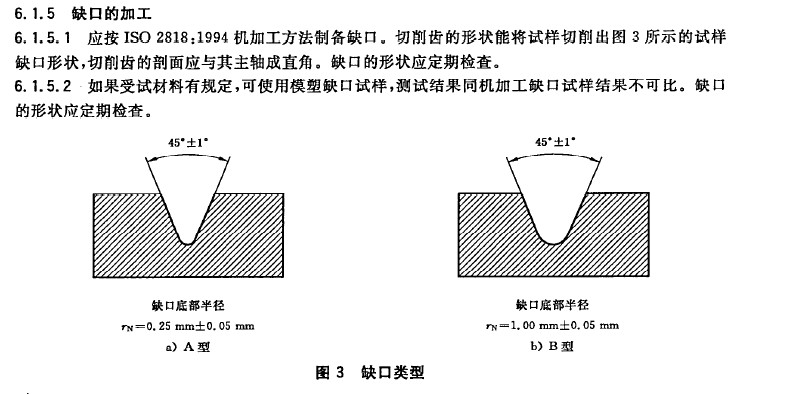
7Sample gap:AType gap 45°±1° Bottom radius of gapR=0.25±0.05mm
BType gap 45°±1° Bottom radius of gapR=1±0.05mm