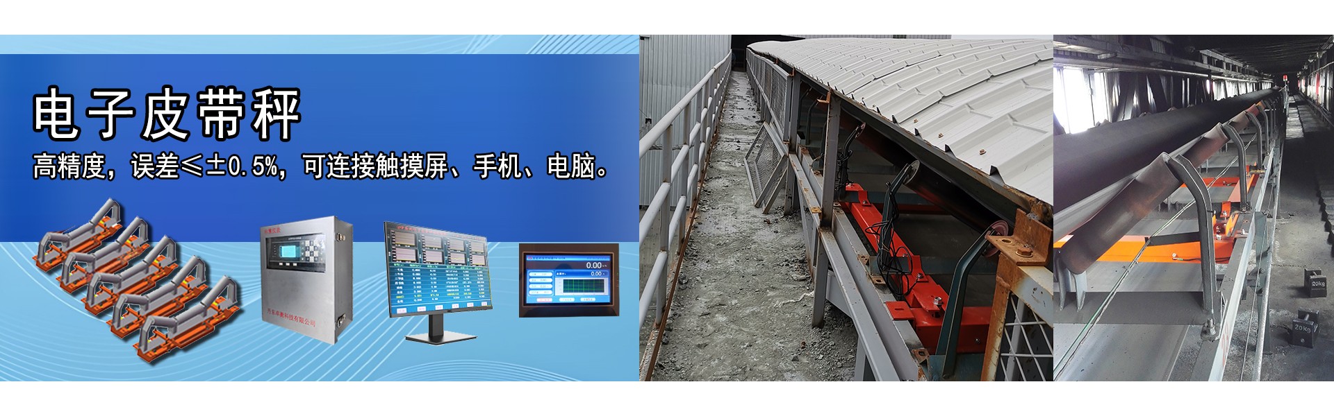
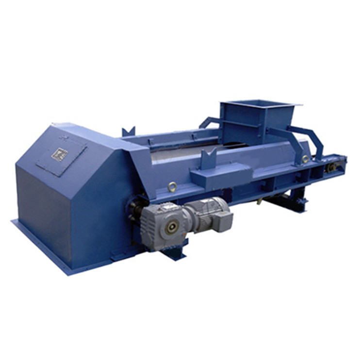
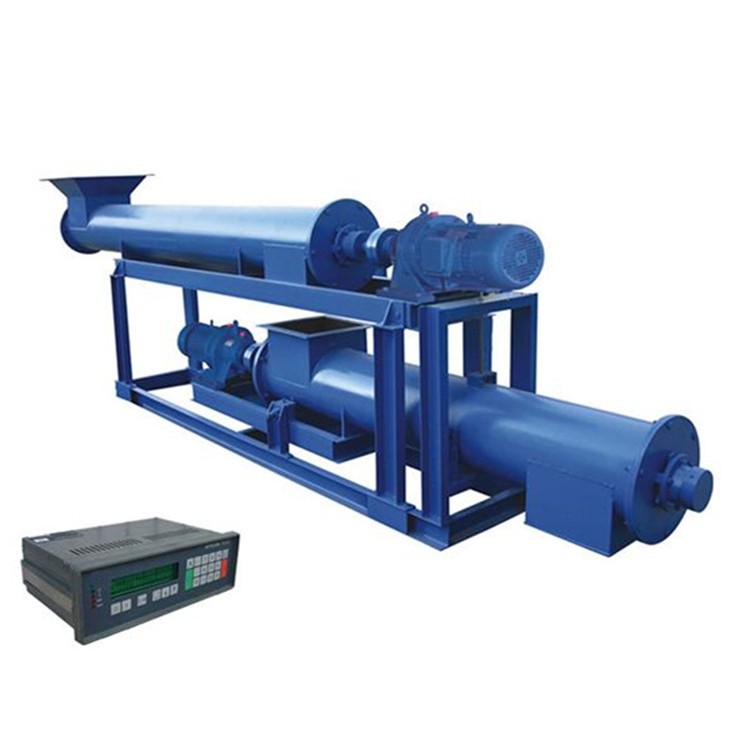
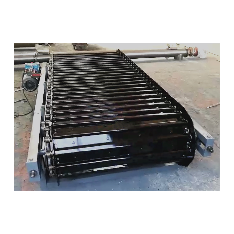
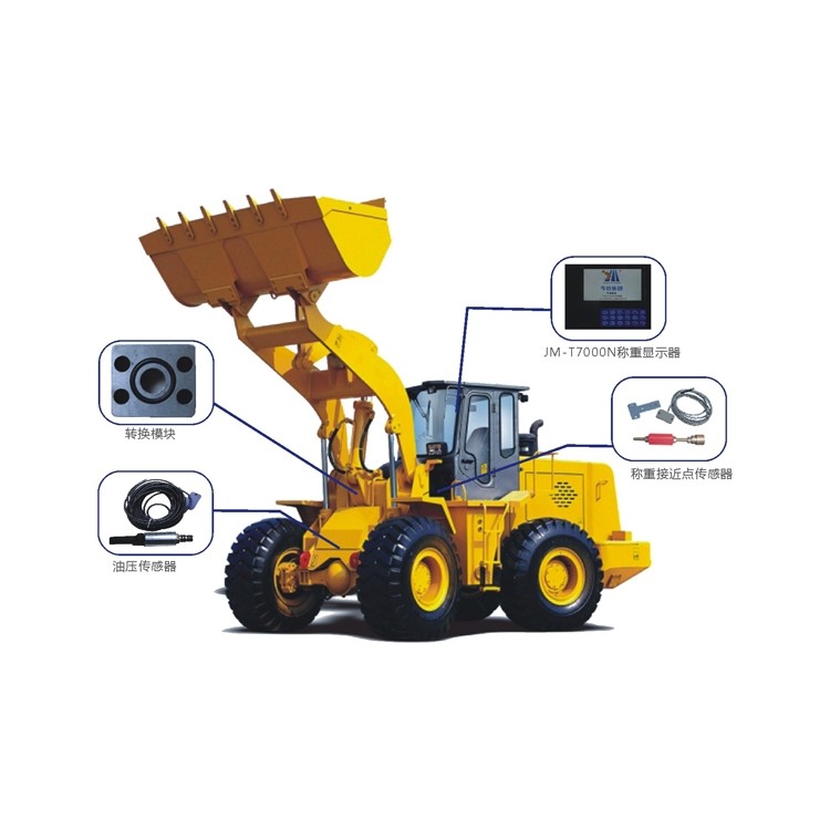
Electronic belt scales, hopper scales, packaging scales, ...

PIDPID control is a commonly used method in industrial production, and the PID调节仪表 is also one of the frequently utilized instruments in industrial control. PID is suitable for systems requiring high-precision measurement and control, as it can automatically calculate the PID control parameters based on the controlled object.
PIDThe Parameter Self-Tuning Controller can be configured for external setpoint (or valve position) control functionality. It can replace servo amplifiers to directly drive actuators (such as valves). The PID external setpoint (or valve position) controller can automatically follow external setpoint values (or valve position feedback values) for control output (analog control output or relay forward/reverse control output). It can achieve automatic/manual switching without disturbance. When switching from manual to automatic, an approach method is used for calculation to ensure a smooth transition between manual and automatic modes. The PID external setpoint (or valve position) controller can simultaneously display measurement signals and valve position feedback signals.
PIDThe Light Column Display Controller integrates digital and analog meters, allowing for digital display of measurement values and control target values (with dual-LED digital display) while simultaneously providing relative analog display of both (with dual light columns). The display mode is a combination of dual-LED digital and dual-light column analog, making the measurement value display clearer and more intuitive.
PIDThe parameter self-tuning controller allows for flexible changes in the input signal type of the instrument. Using a no-jumper technology, simply set the internal parameters of the instrument to switch between different input signals. It offers a choice of a single-channel analog control output (or switch control output, relay, and SCR forward/reverse control) and a single-channel analog transmittal output, making it suitable for various measurement and control applications. It supports multi-machine communication and has various standard serial bidirectional communication functions, with options for multiple communication methods such as RS-232, RS-485, RS-42, and communication baud rates ranging from 300 to 9600 bps. Internal parameters of the instrument can be freely set. It can communicate with various devices featuring serial input/output (such as computers, programmable controllers, PLCs, etc.), forming a management system.
1.PIDCommon Proverb:
Parameter tuning involves searching in ascending order from the smallest to the largest.
First proportion, then integration, and finally, the addition of differentiation.
The curve oscillates frequently; the proportioning dial needs to be enlarged.
Curve floats around the bay, ratio dial turns smaller
Curve deviation response slow, points time decreasing
The curve fluctuation cycle is long, and the integration time is further extended.
The frequency of the curve oscillation is high; first, reduce the differential.
Large differential movement with slow fluctuation. The differential time should be extended.
Two waves of Ideal Curve, high at the front and low at the back, 4 to 1 ratio
A look, a tune, and plenty of analysis – the quality adjustment won't be low.
2.PIDEngineering Tuning of Controller Parameters
Reference the following empirical data for P.I.D parameters in various control systems:
Temperature T: P=20~60%, T=180~600s, D=3-180s
Pressure P: P = 30~70%, T = 24~180s
Level L: P=20~80%, T=60~300s
Traffic F: P=40~10.0%, T=6~60s
Principles and Features
In practical engineering applications, the widely-used regulatory control method is Proportional-Integral-Derivative (PID) control, commonly referred to as PID regulation. The PID controller has a history of nearly 70 years since its inception. It has become one of the main technologies in industrial control due to its simple structure, good stability, reliable operation, and ease of adjustment. When the structure and parameters of the controlled object cannot be fully grasped, or when mathematical models are unavailable, and other control theory techniques are difficult to apply, the structure and parameters of the system controller must be determined based on experience and on-site debugging, making the application of PID control technology convenient. In other words, when we have an incomplete understanding of a system and its controlled object, or are unable to obtain effective measurements to acquireSystem ParametersAt this point, PID control technology is appropriate. In practice, there are also PI and PD controls. A PID controller calculates the control variable based on the system error, utilizing proportional, integral, and differential calculations for control.
Proportion (P) Control
Proportional control is a simple control method. The output of its controller is proportional to the error signal between input and output. When only proportional control is in place, the system output exhibits steady-state error.
Points (I) Control
In integral control, the controller's output is proportional to the integral of the error signal. For an automatic control system, if there is a steady-state error after reaching a steady state, the control system is termed as having steady-state error, or simply, a system with error (System with Steady-state Error). To eliminate steady-state error, an "integral term" must be introduced into the controller. The integral term depends on the integral of the error over time, and as time increases, the integral term grows. Consequently, even with a small error, the integral term increases over time, driving the controller's output to increase and further reduce the steady-state error until it reaches zero. Thus, a Proportional-Integral (PI) controller can ensure the system has no steady-state error upon reaching a steady state.
Differential (D) Control
In differential control, the controller's output is proportional to the derivative of the input error signal (i.e., the rate of change of the error). During the adjustment process of an automatic control system to overcome errors, oscillations or instability may occur. This is due to the presence of significant inertia components (elements) or lagging (delay) components, which have a suppressive effect on the error, always lagging behind the error's change. The solution is to make the suppression of the error's effect "predictive," meaning that when the error approaches zero, the suppressive effect should be zero. This implies that simply introducing the "proportional" term in the controller is often insufficient, as the proportional term only amplifies the magnitude of the error. What is needed now is the addition of the "derivative term," which can predict the trend of the error's change. With a proportional+derivative (PD) controller, the suppression of the error can be made zero or even negative in advance, thus avoiding severe overshoot of the controlled quantity. Therefore, for controlled objects with significant inertia or lag, a proportional+derivative (PD) controller can improve the system's dynamic characteristics during the adjustment process.
PIDController Parameter Tuning
PIDController parameter tuningControl System DesignThe core content involves determining the proportional, integral, and derivative parameters of a PID controller based on the characteristics of the controlled process.
PIDThere are many methods for controller parameter tuning, which can be summarized into two main categories: First is the theoretical calculation tuning method, which primarily relies on the mathematical model of the system to determine controller parameters through theoretical calculations. The computed data obtained from this method may not be directly applicable and requires adjustment and modification through engineering practice. Second is the engineering tuning method, which depends heavily on engineering experience and is conducted directly during system testing. This method is simple and easy to master, making it widely used in engineering applications.
PIDEngineering Tuning Methods for Controller Parameters, mainly including the Critical Proportional Method,Reactive CurveThe法和attenuation methods. Both methods have their unique characteristics, with their commonality lying in the process of experimentation, followed by engineering application.Experience FormulaTuning of controller parameters is conducted. However, regardless of the method used to obtain the controller parameters, they require adjustment and refinement during actual operation. Currently, the critical proportional method is generally employed.
The steps for tuning the PID controller parameters using this method are as follows:
Firstly, pre-select a sufficiently short sampling period to allow the system to operate.
(2) Simply incorporate the proportion control stage until the system exhibits critical oscillation in response to the input step, noting the proportion amplification coefficient and the critical oscillation period at this point.
(3) At certainControl MeasureThe parameters of the PID controller were obtained through formula calculation.
PIDControl Achieved
PID No Chinese content provided.
Varying inverters have different names for their feedback logic, even with similar names that have opposite meanings. When designing the system, refer to the manual of the selected inverter. Feedback logic refers to the control polarity of the output frequency of the inverter, based on the feedback signal detected by the sensor of the controlled physical quantity. For instance,Central Air Conditioning SystemIn our company, we use the return water temperature to control and adjust the frequency of the variable-frequency inverter and the speed of the water pump motor. During winter heating, if the return water temperature is low, the feedback signal decreases, indicating that the room temperature is low, and we need to increase the output frequency of the inverter and the speed of the motor to boost the flow of hot water. Conversely, during summer cooling, if the return water temperature is low, the feedback signal decreases, indicating an excessively low room temperature, and we can reduce the output frequency and motor speed to decrease the flow of cold water. As shown above, although a low return water temperature and a decreased feedback signal both occur, the direction of frequency change required for the inverter is opposite. This is the reason for introducing feedback logic.
Enable PID Function
To enable the PID control function in a closed-loop system, the PID function must first be preset as active. There are two specific methods for this: 1. Through the functional parameter codes of the inverter, for example, with the KONWEI CVF-G2 series inverters, setting parameter H-48 to 0 disables the PID function; setting it to 1 enables standard PID control; and setting it to 2 activates the constant pressure water supply PID. 2. By the state of the external multi-functional terminal of the inverter. For instance, with the YASKAWA CIMR-G 7A series inverters, as shown in Figure 1, selecting any of the multi-functional input terminals Sl-S10 and presetting the function code H1-01 to H1-10 (corresponding to terminals S1-S10) to 19 will enable the terminal to determine the effectiveness of PID control. This terminal is ineffective when connected to the common terminal SC "ON" and effective when "OFF". It should be noted that most inverters have both presetting methods, but some brands only offer one of the two.
In systems with less stringent control requirements, it is sometimes sufficient to use only the PI control function without activating the D function to meet the needs, making the system debugging process relatively simple.
Target Signal & Feedback Signal
To maintain a specific physical quantity in the variable-frequency system at the desired target value, the PID function circuit of the variable-frequency drive continuously compares the feedback signal with the target signal and adjusts the output frequency and the motor's speed in real-time based on the comparison results. Therefore, the PID control of the variable-frequency drive requires at least two control signals: the target signal and the feedback signal. The target signal referred to here is the electrical signal corresponding to the expected stable value of the physical quantity, also known as the target value or setpoint. The electrical signal corresponding to the actual value of the physical quantity measured by the sensor is called the feedback signal, also known as the feedback quantity or the current value. The functional block diagram of the PID control is shown in Figure 2. It includes a PID switch. The PID function can be enabled or disabled by setting the function parameters of the variable-frequency drive. When the PID function is active, the PID circuit determines the operating frequency; when the PID function is inactive, the operating frequency is determined by the frequency setting signal. The working status of the PID switch, action selection switch, and feedback signal switch are all determined by the settings of the function parameters.
Target Values Set
How to transmit command information for the target value (target signal) to a variable frequency drive, various drives employ different methods, but generally, there are two main approaches: one is the automatic conversion method, where when the variable frequency drive's pre-set PID function is active, the frequency setting function during open-loop operation automatically switches to target value setting, as seen in the Hitachi CIMR-G 7A and the Fuji P11S variable frequency drives in Table 2. The other is the channel selection method, as demonstrated by the Kanco CVF-G2, Senlan SB12, and Putian P17000 series variable frequency drives in Table 2.
Next, we need to determine the size of the target value. Since the target signal and feedback signal are typically not the same physical quantity, a direct comparison is difficult. Therefore, most variable frequency drives express the target signal as a percentage of the sensor's range. For example, if the air pressure in a gas storage tank needs to be stabilized at 1.2 MPa, and the pressure sensor's range is 2 MPa, the corresponding percentage for 1.2 MPa would be 60%, making the target value 60%. In some variable frequency drives, the parameter list includes values corresponding to the upper and lower limits of the sensor range, such as the Fuji P11S variable frequency drive. Setting parameter E40 (display coefficient A) to 2 corresponds to the upper limit of the pressure sensor range, 2 MPa, and setting parameter E41 (display coefficient B) to 0 corresponds to the lower limit of 0. In this case, the target value is 1.2, meaning the pressure stabilization value is 1.2 MPa. The target value is essentially the expected stable value.Please provide the Chinese content to be translated into American English.。
Feedback Signal Connection
Each variable-frequency inverter has several frequency set input terminals. Among these input terminals, if one has been determined as the input channel for the target signal, the others can be used as input terminals for the feedback signal. One can select and use one of them by setting the corresponding function parameter code. Table 3 lists several typical variable-frequency inverters' feedback signal channel selection options.
PID Parameter Presetting and Adjustment
Proportional Gain P
The PID function of a variable-frequency inverter adjusts the output frequency by utilizing the difference between the target signal and the feedback signal. On one hand, we aim for the target and feedback signals to be as close as possible, with a minimal difference, to ensure precise adjustment. On the other hand, we also want the adjustment signal to have a certain amplitude to ensure sensitivity. The solution to this contradiction is to amplify the difference signal beforehand. The proportional gain P is used to set the amplification coefficient of the difference signal. Any variable-frequency inverter's parameter P provides a range of adjustable values, usually preset to a slightly higher middle value during initial debugging, or temporarily set to the factory default value, which can then be fine-tuned according to actual conditions during operation.
Point Time
As mentioned above, the higher the proportional gain P, the higher the adjustment sensitivity. However, due to the inertia of the transmission system and the control circuit, the adjustment cannot stop immediately upon reaching the set value, resulting in "overshoot." This is followed by a reverse adjustment, leading to another overshoot and forming an oscillation. To address this, an integral term I is introduced, which causes the difference signal amplified by the proportional gain P to gradually increase (or decrease) within the integration time, thus slowing down its rate of change and preventing oscillation. However, if the integration time I is too long, it becomes difficult for the controlled physical quantity to quickly recover when the feedback signal changes abruptly. Therefore, the value of I is related to the time constant of the driving system: when the time constant of the driving system is small, the integration time should be shorter; when the time constant is large, the integration time should be longer.
Differential Time D
Differential time D is determined based on the rate of change of the differential signal, providing an appropriate adjustment action in advance to shorten the adjustment time and overcome the defect of recovery lag caused by excessively long integration time. The value of D is also related to the time constant of the drive system: when the time constant of the drive system is smaller, the differential time should be shorter; conversely, when the time constant of the drive system is larger, the differential time should be longer.
PID Principle of Parameter Adjustment
P The preset values for I and D parameters complement each other. On-site operation should be fine-tuned according to actual conditions as follows: if the controlled physical quantity oscillates around the target value, first increase the integral time I. If oscillations persist, reduce the proportional gain P slightly. If the controlled physical quantity is difficult to recover after a change, increase the proportional gain P first. If recovery is still slow, decrease the integral time I slightly and increase the derivative time D.


b2b.china9.net © Zhongshang 114 Hebei Network Technology Co., Ltd.Address: Room 6009, Oriental New World Center, No.118 East Zhongshan Road, Qiaoxi District, Shijiazhuang City, Hebei ProvincePlatform Service Hotline: 4006299930