

- AllProduct Category
-
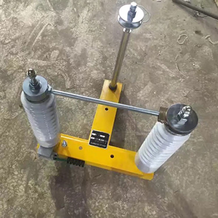
High Voltage Isolation Disconnect Series
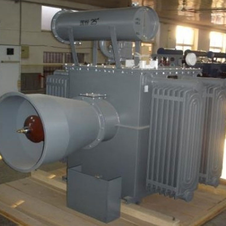
High-Voltage Silicon Rectifier Transformer Series
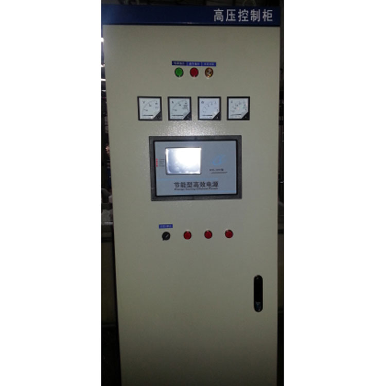
High-Voltage Power Series
High Voltage Isolation Switch Box Series
Electrostatic Dust Removal Controller
Dust Collector Series
Insulating Porcelain Components
Top Drive Side Impact Device
Cathode Ray Series
Pneumatic Conveying System
Dust Collector Additional Parts


详情描述
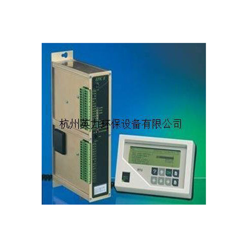
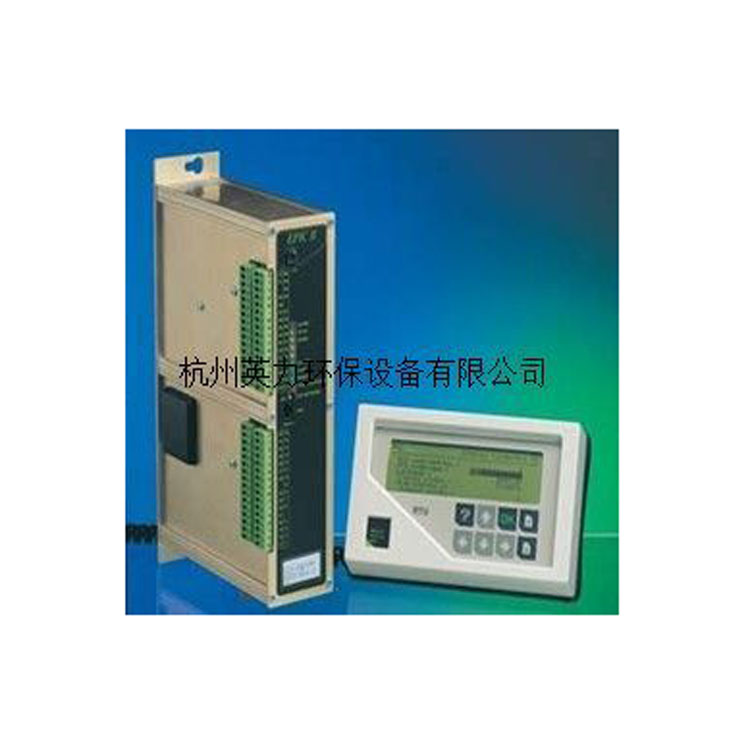
EPIC-II Electrostatic Dust Removal Controller
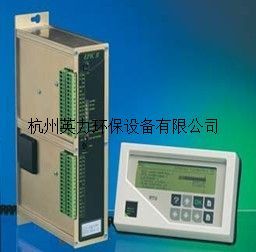
Product Description
The operational process of the control system is as follows:
The primary current and voltage signals and the secondary current and voltage sampling signals, after being amplified by an operational amplifier, are combined with three setpoint signals (manual, rise rate, and current limit) and then converted into digital signals by an ADC for processing by the CPU.
The CPU, based on the control mode set by the switch, determines the conduction angle of each half-wave according to different algorithms, and then starts the timer at the corresponding timing value to output the SCR phase-shift triggering pulse. The triggering pulse is sent to the SCR triggering board via the gate control circuit, isolated and triggered by a photo-controlled thyristor and synchronized by a synchronous transformer, resulting in two identical power supply half-wave synchronous thyristor triggering signals.
When a flashover occurs in the electric field, the peak current of the flashover is compared with the reference value output by the D/A converter to determine the intensity of the flashover (spark) and to emit a spark interruption signal. Upon responding to the spark interruption, the CPU determines whether to shut down the SCR and the conduction angle for each half-wave of the recovery process based on the intensity of the spark.
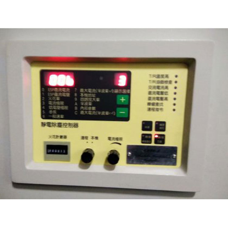
Six LED displays are managed by the keyboard and 8279 display interface chip, showing operational parameters, fault types, and setup procedures during operation.
The 8255 parallel interface circuit handles both the operation key signal input and the printer interface functions.
The control system operates in synchronization with the zero-crossing signals generated by the zero-crossing pulse circuit.
询价单


