

- AllProduct Category
-
Wood Steam Drying Equipment
Wood Drying, Drying Chambers
Brick-and-Mortar Wood Drying Kiln
Wood Product Heat Treatment Equipment
Redwood Drying, Kiln
Wood Deoiling and Drying Equipment
Container Wood Drying Machine
Aluminum Alloy Wood Drying Oven
Monoblock Drying Equipment Set
Wood Temperature Control & Health Preservation Room
Wood Reclamation Equipment
Wood Drying Equipment Accessories
Mahogany Drying Oven Dual Fuel Type
Rosewood High-Frequency Vacuum Drying Machine
Rosewood Wax Injection Machine, Rosewood Wax Boiling Machine
Carbonized Wood Equipment
Air Source Heat Pump Dryer
Tumbler Dryer
Heating Core (Furnace)
Vacuum Drying Equipment


详情描述
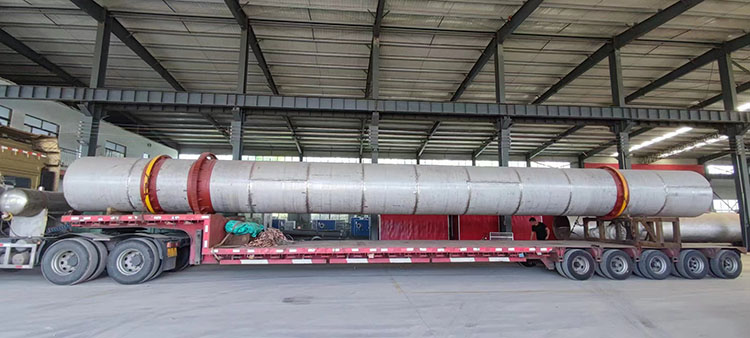
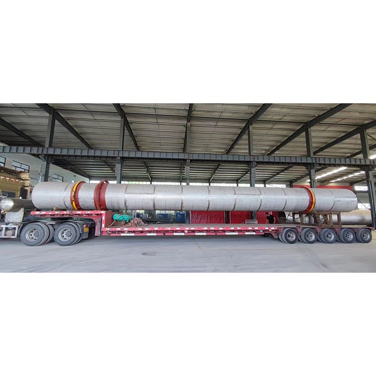
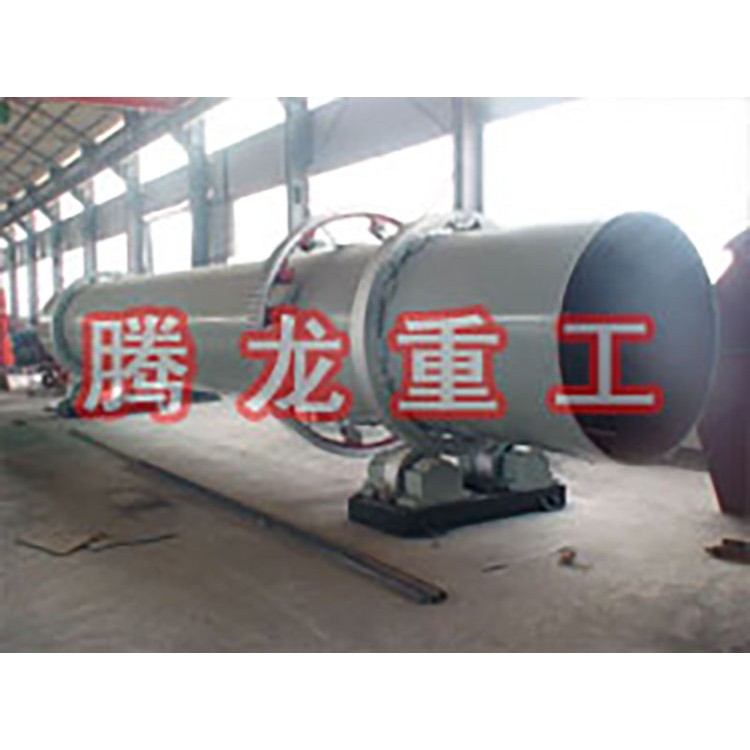
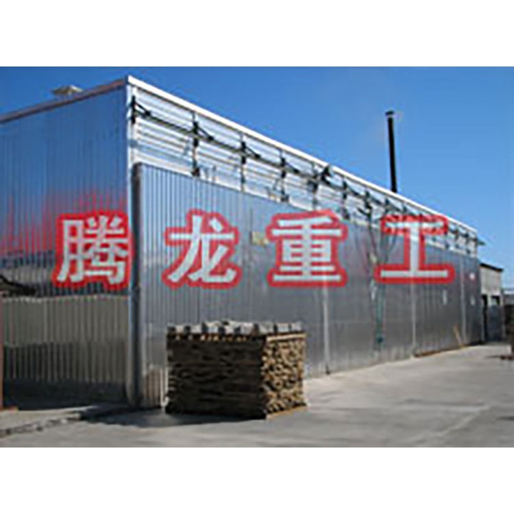
Tunnel dryer:
Ore concentrates such as magnetic, gravity, and floatation concentrates, as well as clays for the cement industry and coal slime from the coal mining industry. It is characterized by high production rates and ease of operation. The drum dryer features a horizontal rotating cylinder with various types of scrapers welded at different angles from front to back. Inside the rotary kiln, different types of refractory bricks are inserted according to requirements, and a door ring and spiral scraper are provided at the feed end to prevent backflow. It boasts advantages such as rational structure, excellent craftsmanship, high output, low energy consumption, and convenient operation.
Category Editing
Direct Heat Drum Dryers (where the drying medium and wet material come into direct contact to transfer heat) and Indirect Heat Drum Dryers (where the required heat for drying is indirectly transferred to the wet material through the drum wall) are categorized based on the heat transfer method between the drying medium and wet material. Due to the low transfer efficiency and complex structure of indirect heat drum dryers, they are rarely selected and will not be introduced here.
Direct heat drum dryer, divided into two types according to the direction of the drying medium and material flow: co-current and counter-current.
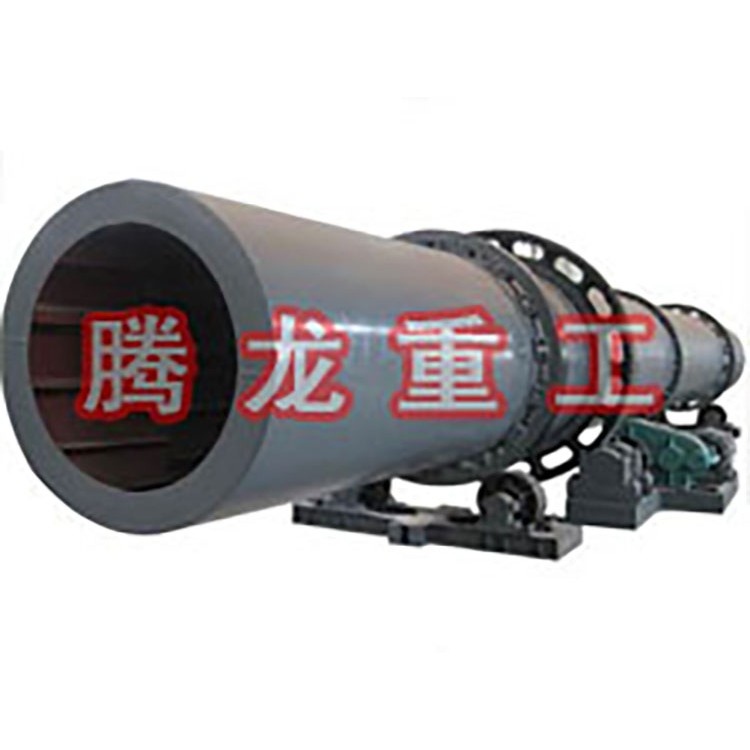
The main part of the direct heat rotating drum dryer consists of a rotating cylinder slightly inclined from the horizontal line. The cylinder is driven by gears, with a rotation speed typically ranging from 2 to 6 r/min. The inclination of the cylinder is related to its length, usually between 1° to 5°. Materials are fed into the higher end of the drum, come into contact with hot air, and as the cylinder rotates, the materials flow under gravity to the lower end, where they are dried and discharged. Since the dryer operates under negative pressure, both the feeding and discharging ends are equipped with sealed devices to prevent air leakage.
Internal Structure Editor
To ensure uniform distribution of the material and good contact with the drying medium across all parts of the drum cross-section, an agitator plate is installed inside the drum. The types of agitator plates include:
One: Elevating Sliding Gate: Suitable for large pieces of material or material that tends to stick to the drum wall.
Two and Four Section Aerator: Suitable for dense, non-friable, or non-easily dispersible materials. This aerator divides the cylinder into four sections, forming four separate, non-communicating sector-shaped operation chambers. It offers a larger contact area with hot gases compared to the lifting-type aerator, and can also increase the filling rate of the material and reduce the descent height of the material, thereby decreasing dust loss.
Three: Cross or frame-type elevator blades: Suitable for fragile and easily scattered small pieces of material, allowing the material to be evenly distributed across the entire cross-section of the cylinder.
Four,筒式扬板: The aeration plate for a double heat transfer (or semi-diameter heating) drum dryer.
V. Spiral Blade Design (Spiral Type) is suitable for materials with very fine particles that are prone to dust generation. Once the material is introduced, it accumulates on the tray. As the drum rotates, the material is agitated and continuously comes into contact with hot gases. Additionally, the reduced drop height of the material minimizes the possibility of dried material being carried away by the gases.
The various types of distributors can be distributed throughout the cylinder. To ensure that materials are delivered quickly and relatively evenly to the distributors, spiral distributors can also be installed at 1~5m from the feeding end to prevent wet materials from sticking and accumulating on the cylinder walls. Additionally, since dried materials are easily lifted and carried away by exhaust gas, distributors are not installed at 1~2m from the discharge end.
Operating Principle
Dry wet material is conveyed to the hopper by a belt conveyor or a bucket elevator, then it enters the feeding end through the hopper's feeding machine via a feeding pipeline. The slope of the feeding pipeline must be greater than the natural angle of repose of the material to ensure smooth flow into the dryer. The dryer cylinder is a rotating cylinder slightly inclined from the horizontal line. Material is added from the higher end, while the heat carrier enters from the lower end, contacting the material in a countercurrent manner; sometimes, the heat carrier and material flow together into the cylinder. As the cylinder rotates, the material moves under gravity to the lower end. During its forward movement within the cylinder, the wet material is directly or indirectly heated by the heat carrier, allowing it to dry. Then, it is discharged at the outlet end via a belt conveyor or a screw conveyor. Scrapers are mounted on the inner wall of the cylinder, which function to lift and scatter the material, increasing the contact surface with the airflow to enhance drying speed and promote material movement. Heat carriers typically include hot air, flue gas, etc. After passing through the dryer, the gas is usually captured by a cyclone separator to remove the material carried within it. To further reduce the dust content in the exhaust gas, it should pass through a baghouse or a wet scrubber before being released.
Features Edit
The drying machine produced with a multi-composite feeding device design has undergone numerous technical innovations in the feeding device system. It employs a new multi-composite feeding device, overcoming the "wind tunnel" phenomenon of traditional drying machines, with high thermal efficiency and a reduction in coal consumption of about 20%.
2. Suitable for multiple types of burners: high-temperature boiling furnaces, coal-milling spray furnaces, and manual coal-adding furnaces.
3. The transmission uses replaceable pinion gears instead of traditional cast steel gears, saving on cost and investment while significantly reducing maintenance costs and time.
4. Utilizes a centralized control system for microcomputer central monitoring and management in large enterprises.
5. Enhanced production capacity, capable of continuous operation.
6. Simple structure, easy to operate.
7. Few malfunctions, low maintenance costs.
8. Wide application range; suitable for drying granular materials, particularly beneficial for materials with strong adhesion.
9. High operational flexibility allows for a wide range of product output fluctuations without compromising quality.
10. Easy to clean.
Application Scope
Tunnel dryers are primarily used for drying granular and powdered materials in industries such as chemicals, metallurgy, building materials, and mining.
Screw Dryer Operation Process
The drying medium of the direct heat transfer drum dryer is usually flue gas. The countercurrent direct heat transfer drum dryer has its combustion chamber and wet material feed point at the same end. The movement direction of the hot gas flow is consistent with that of the material. As the wet material moves from the feed end to the discharge end, it is heated and dried by the hot air, which flows from the feed end to the discharge end, powered by the blower and induced draft fan.
Counter-current direct heat transfer drum dryer, where wet material is introduced into the dryer at the feeding end, the combustion chamber is located at the discharge end, and the material moves in the opposite direction to the drying medium (hot air). The material is heated and dried during this process.
The flow-through drying method, where wet material comes into contact with higher-temperature drying medium as it enters the dryer, initially provides a strong drying drive. As the material temperature increases, the drying medium's temperature decreases. Therefore, it is suitable for materials that do not require high final moisture content (i.e., drying level). The discharged dry material has a lower temperature, making transportation easier. However, it tends to generate more dust due to fine material being easily carried away by the air flow. Counter-current drying maintains a uniform drying drive throughout the process, making it ideal for materials that require stricter drying conditions. The dust carried by the drying medium is filtered in the wet material zone, resulting in a lower dust content in the air flow. The specific drying method chosen depends on the requirements of the material to be dried.
Technical Parameters Editing
Usage Instructions
The installed dryer should undergo a non-load trial run of not less than 4 hours, and any abnormal conditions during the trial run should be addressed promptly.
After the trial operation, retighten all the connecting bolts again, check and replenish the lubricating oil, and proceed with the load test once the normal rotation is achieved.
Prior to the load test run, each auxiliary equipment should be tested individually with the empty vehicle. Once the individual test run is successful, proceed to the joint test run.
Ignite the hot air furnace dryer to preheat, and simultaneously start the dryer. Prohibit heating without the cylinder rotating to prevent cylinder bending.
Based on the preheating status, gradually add wet material to the drying cylinder, and incrementally increase the feeding rate according to the moisture content of the discharged material. Preheating the dryer requires a process, as does the preheating of the hot air furnace; avoid sudden intense burning. Prevent localized overheating and uneven thermal expansion that may cause damage.
The fuel's calorific value, the quality of insulation in each part, the moisture content in the wet material, and the uniformity of the feed rate all affect the quality of the dried product and the fuel consumption. Therefore, ensuring that each part is as good as possible is an effective way to enhance economic benefits.
During operation, the wheel stand frame should be filled with cooling water. All lubrication points should be timely oiled.
Ensure the hot air furnace is turned off before parking, and keep the drying cylinder rotating until it cools to nearly ambient temperature before stopping. Prohibit parking at high temperatures to prevent warping and deformation of the cylinder.
In the event of a sudden power outage, immediately extinguish the hot air furnace and stop feeding. Rotate the drum by half a turn every 15 minutes until it cools down. This procedure should be strictly monitored by a designated person, as violating it can cause the drum to bend. Severe bending of the drum will render the dryer unusable.
Faults and Solutions
The discharged material has an excessive moisture content. At this point, increase the fuel consumption or simultaneously reduce the feed rate.
The discharged material has an excessively low moisture content. At this point, it is advisable to reduce the fuel consumption or simultaneously increase the feed quantity.
This operation should be gradually adjusted to an appropriate state. Sudden adjustments can cause fluctuations in the moisture content of the material, failing to meet the quality requirements of the product.
2. Both idler wheels experience repeated heavy loads. This phenomenon requires checking the contact between the idler and support wheel belts. Misalignment of the same set of idler wheels or the line connecting the two idlers not being perpendicular to the cylinder's axis can cause excessive load on the idler wheels, as well as abnormal wear on the idlers.
3. This issue is often due to low installation accuracy or loose bolts, causing the idler wheel to deviate from its proper position during operation. Restoring the idler wheel to its correct position will eliminate this phenomenon.
3. Abnormal sounds are emitted from the large and small gears in operation. It is then necessary to check the meshing clearance between the large and small gears. Adjusting to the proper setting will restore normal operation.
Severe wear on small gears should be replaced promptly.
The gear cover is well-sealed to prevent dust from entering, and an ample, reliable lubricant is crucial for extending the gear's lifespan. A thick gear oil or black oil should be added inside the large gear cover.
Primary Standard Parts Editor
1. Roller Bearing, Model: 320, Installed in Trolley Wheel
2. Roller Bearing, Model: 7218, Installed in the Flange Wheel
3. Roller Bearings, Model: 3622, fitted in small gear bearing housing
4. Rubber Oil Seal 100×130×12
5. C-Type V-Belt 1800
Installation and Maintenance
Machine maintenance and care is an important and regular task, which should be closely coordinated with operations and inspections, and should have a dedicated staff.
Employees conduct on-duty inspections.
Machine maintenance
1. Bearings: The shaft of the drum drier bearing bears the full load of the machine. Therefore, good lubrication is crucial for the bearing's lifespan, directly affecting the machine's performance.
The lifespan and operational efficiency of the equipment necessitate that the lubricating oil injected be clean and well-sealed. The primary oiling point of this machine is located at (1)
Ball bearings (2) Roller bearings (3) Gears (4) Sliding bearings, sliding planes.
2. Newly installed wheel nuts are prone to loosening; they should be checked frequently.
3. Ensure all machine components are functioning properly.
4. Pay attention to the wear degree of easily worn parts and always replace worn components as needed.
5. The flat surface of the base for the activity device should be free of dust and other debris to prevent the moving bearing from failing to operate properly when the machine encounters materials that cannot be crushed.
The item was moved upwards, resulting in a severe accident.
6. Increase in bearing oil temperature requires immediate shutdown for inspection and cause elimination.
7. If there is a knocking sound when the gear is in operation, stop immediately and inspect. The steps for elimination and adjustment are as follows:
As the cylinder moves downward, tighten bolt 2 one turn and loosen bolt 1 one turn (note: the number of turns must be equal), the cylinder will stop descending; if moving upward in the opposite direction, add liquid lubricant to the roller. The cylinder will stop ascending. If it still ascends, tighten bolt 1 and loosen bolt 2, the cylinder will stop ascending; if it moves downward again, wipe off the lubricant from the roller. If necessary, repeat the aforementioned method until it stops moving erratically. During adjustment, prevent the roller from tilting in different directions.
During the adjustment process, to raise the drum of the drum dryer, pour some lubricating oil on the surface of the idler wheel to increase the surface friction; conversely, to lower the drum, apply some thick grease to reduce the surface friction. Adjusting the idler wheel requires adjusting all four simultaneously, ensuring that the belt contacts the idler wheel for at least 50%.
The drum dryer, after adjusting the idler wheel, significantly reduces the load on the blocking wheel, thereby extending the lifespan of the discharge and blocking wheel bearings. This reduction in production costs and improved efficiency is achieved. While wear is inevitable during operation, regular maintenance, lubrication, and frequent observation of the position of the old and new wheels, as well as the bearing heat situation, and timely adjustments and repairs are necessary to ensure smooth production.
Installation and trial run
1. The equipment should be installed on a level concrete foundation and secured with anchor bolts.
2. Pay attention to the vertical alignment of the main body with the level during installation.
3. After installation, check if all bolts are tight and the main storage door is securely fastened. If loose, please tighten them.
4. Configure power cables and control switches according to the equipment's power configuration.
5. After inspection, conduct an empty load test run; proceed to production upon normal operation.


