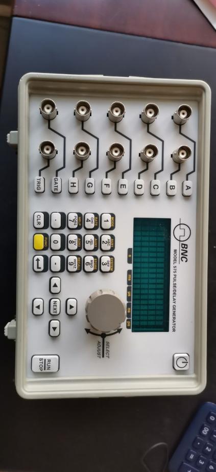
For the maintenance of the BNC Delay Signal Generator 575 8C, here is a systematic troubleshooting and repair guide for reference:
1. Preliminary inspection
Power Verification
Check if the power indicator light is on, confirming normal power supply (such as AC input or battery).
Measure the output voltage with a multimeter to ensure it meets the specifications (such as ±15V, +5V, etc.).
If power is abnormal, inspect the wire, rectifying circuit, voltage stabilizing chip (such as LM317), and filtering capacitors (for bulging or leakage).
Appearance inspection
Inspect for any burnt components, cracked solder joints, loose connectors, or PCB corrosion marks.
Gently shake the equipment to listen for any loose internal parts (such as relays, transformers).
2. Common Faults and Repair Procedures
A. No output signal
Signal Path Inspection
Trace the signal back from the output end using an oscilloscope, and check each stage of the circuit (such as delay lines, amplifiers, switch ICs) sequentially.
Key test for delay lines (such as SAW devices in SMD packages) to ensure no damage (no delayed output after input signal).
Check the switching status of the relay or analog switch (such as the DG series) for normal operation.
Troubleshooting Control Circuit
Verify that the microprocessor/FPGA is operating (check clock signals, reset circuit).
Test the DAC (such as AD9767) output for normalcy, and verify the accuracy of the voltage/current used for setting the delay time.
B. Output Signal Distortion/High Noise
Simulation Circuit Debugging
Inspect power supply and output waveform of operational amplifiers (e.g., OP07, AD8620), replace any faulty components.
Check if the RC network of the low-pass filter has deteriorated (increased capacitor ESR, resistive value drift).
Shielding Wire Inspection: Check if the BNC connector is properly grounded and if there are any damages to the internal coaxial cable.
# C. Delay Time Inaccurate
Clock Calibration
Adjust the oscillator or TCXO calibration circuit (may include adjustable capacitors or EEPROM configuration) as referenced in the manual.
Verify the accuracy of pulse counting in the timing control logic circuit (such as counter IC).
3. Component-level repair techniques
Key Component Replacement
Delay Line: If damaged, replace with the original factory or an equivalent with the same parameters (note delay time and impedance matching).
Aged Capacitors: Focus on replacing electrolytic capacitors in the power section (such as Nichicon brand) and MLCCs in the high-frequency area.
Relay contacts: Clean with alcohol or replace (e.g., Omron G6K series).
Welding Precautions
Handle precision components with a constant-temperature soldering iron (temperature ≤ 300℃) to prevent static damage.
Be cautious when desoldering multilayer PCBs to prevent hole detachment.
4. Calibration and Testing
Delay Accuracy Verification
Input standard pulse signal (such as 10MHz) and measure the delay error using a high-precision oscilloscope (such as Keysight InfiniiVision).
Adjust the potentiometer or calibrate through software (if RS 232/GPIB interface is available).
Temperature Stability Test
Operate under high temperature (50℃) and low temperature (0℃) conditions to observe if the signal drift exceeds the standard.
5. Repair Resources
Manuals and drawings
Contact BNC manufacturers for the Service Manual (some older models may require a fee).
Refer to the circuit design of similar models (e.g., 575 6B).
Alternative Component Procurement
Recommended Platforms: Digi-Key, Mouser (search for key IC models); delay lines are available for quotation at API Technologies.
6. Important Notes
Safe Operation
Discharge high-voltage capacitors (such as large capacity capacitors in power modules) after power failure.
Avoid accidental contact with high-impedance nodes (such as the input end of delay lines), to prevent static damage.
Support
In case of lost FPGA programs or ASIC malfunctions, it is recommended to return the product to the factory for repair.
If more specific fault phenomena are provided (such as error codes, abnormal waveform photos), the troubleshooting scope can be further narrowed down.

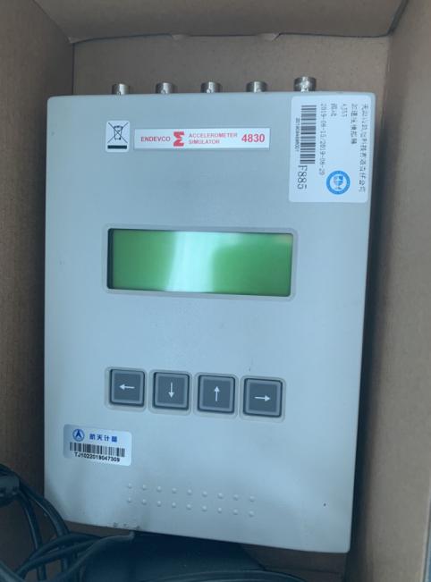 ENDEVCO Vibration Simulator 4830 Maintenance
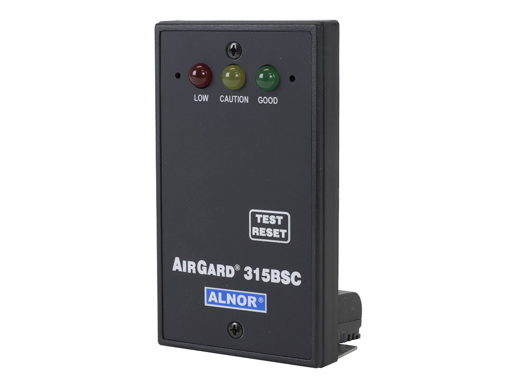 ALNOR Instruments Wind Speed Meter Repair
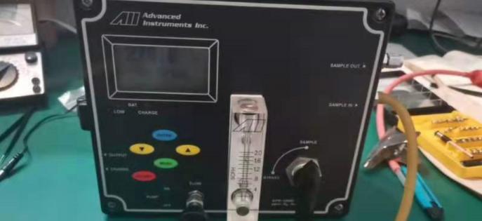 Analyzer GPR-1200 Maintenance

 Brainchild Touchscreen 15HMI2011010-SN Maintenance
 Repair BALDOR Motor 0105300033-000010
 Repair Newark Digital Oscilloscope 54AH4789