For the repair of Hetronik heater controller, here is a systematic solution covering common troubleshooting and repair procedures:
1. Safety Precautions
Power-off Operation: Always disconnect the power source before maintenance to avoid the risk of electric shock.
Antistatic Measures: Use an antistatic wrist strap or touch grounded metal to dissipate static electricity, preventing damage to circuit boards.
Assistance: For high-voltage circuits or complex chip-level repairs, it is recommended to contact or a technician.
2. Common Faults and Repair Procedures
A. Controller Unresponsive (No Display/Not Starting)
Check Power Supply:
Confirm the plug voltage is normal (e.g., 220V), and test the power cable for conductivity with a multimeter.
Check for wire breakage and replace with wire of the same specification.
Motherboard Power Supply Test:
Measure the control panel input voltage (e.g., 12V/24V DC). If there is no output, check the power module or transformer.
Reset operation:
Some models feature a reset button; hold it for 5 seconds to attempt a factory reset.
B. Heating Anomaly (No Heating or Unstable Temperature)
Temperature sensor detection:
Disconnect the sensor connection and measure the resistance with a multimeter (e.g., PT100 at room temperature is about 100Ω). If the resistance is abnormal, it needs to be replaced.
Relay / Solid State Relay (SSR) Testing:
Listen for the relay's click sound; no sound may indicate a damaged coil; use a multimeter to check the contact's continuity.
The SSR can be tested for its output terminals' conductivity through input voltage.
Heating Element Inspection:
Measure the resistance of the heating tube; infinite resistance indicates an open circuit, replacement is required.
# C. Display Error Code
Refer to manual: Match the description or code table (e.g., E1 for temperature sensor failure, E2 for overload).
Targeted Treatment:
If a communication fault (e.g., E5) is reported, check the RS485 line connection or terminal resistance.
# D. Key/Touch Failure
Clean panel: Wipe touch points or areas with alcohol to eliminate oxidation or dirt.
Replace microswitch: Remove faulty button, solder switch of the same type.
3. PCB Repair Techniques
Inspection: Observe capacitor bulging, burnt components, and solder joints with cold soldering (strengthened with solder to reinforce re-soldering looseness).
Key Component Testing:
MCU1: Check if the crystal oscillator is oscillating (measure frequency with an oscilloscope) and the supply voltage (e.g., 3.3V/5V).
MOSFET/IGBT: Use a diode checker to test for gate breakdown.
Line Repair: Use flying wire to connect broken lines; clean corroded areas with alcohol and then apply insulating paint.
4. Replacement Parts Recommendations
Channels: Purchase original factory parts (such as the dedicated control board for model HTC 200) through Hetronik or authorized agents.
Compatibility Notice: Replacement components must match parameters (e.g., relay load current, sensor type).
5. Post-repair testing
No-load power-on: Do not connect the heater first, confirm that the controller display and buttons are functioning normally.
Step-by-step loading: Monitor the temperature control accuracy after connecting the heater (e.g., whether it stabilizes within ±2℃ when set to 50℃).
6. Contact Support Scenarios
If the program chip (MCU) is damaged, firmware burning is required.
Motherboard extensively damaged or failure point undetectable.
Hint: If the model is unknown or the above steps are ineffective, provide the specific model (e.g., HET ABC123) and the symptoms of the failure for further analysis. For safety and complex issues, it is recommended to consult with personnel.

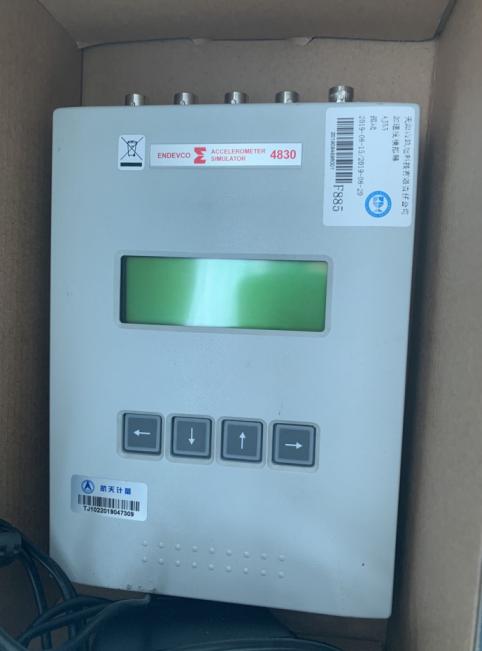 ENDEVCO Vibration Simulator 4830 Maintenance
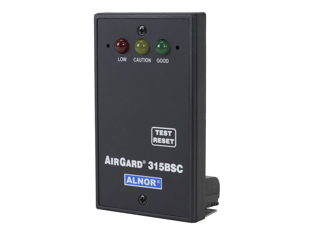 ALNOR Instruments Wind Speed Meter Repair
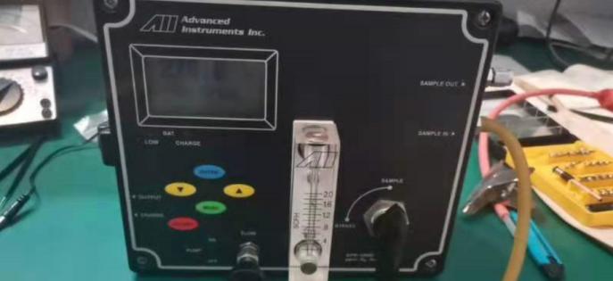 Analyzer GPR-1200 Maintenance

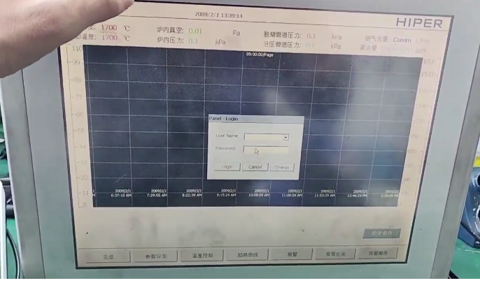 Brainchild Touchscreen 15HMI2011010-SN Maintenance
 Repair BALDOR Motor 0105300033-000010
 Repair Newark Digital Oscilloscope 54AH4789
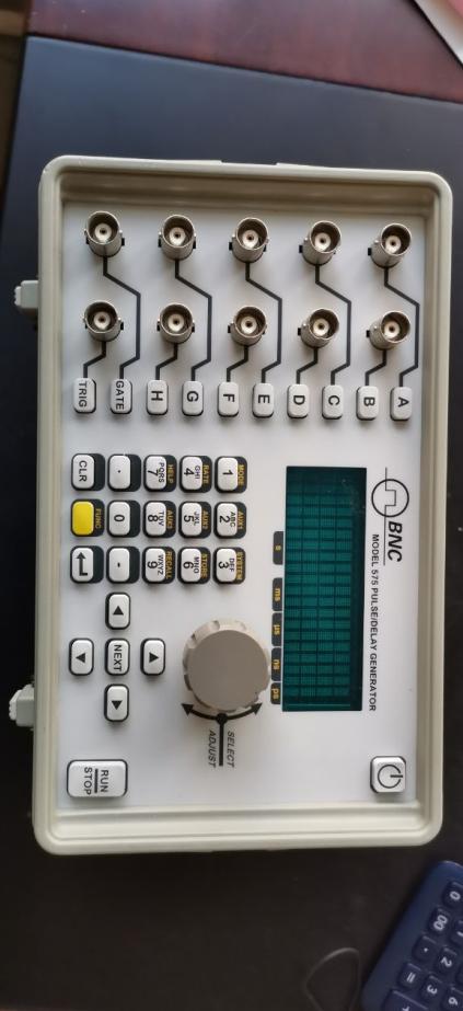 BNC Delay Signal Generator 575-8C Repair