
 Carbonated Beverage Heat Exchanger Set
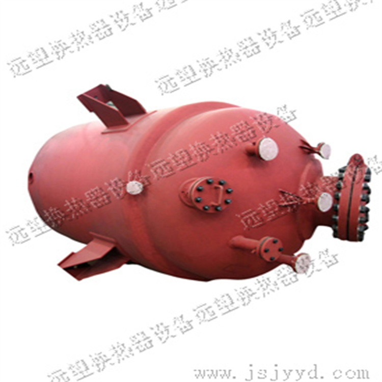
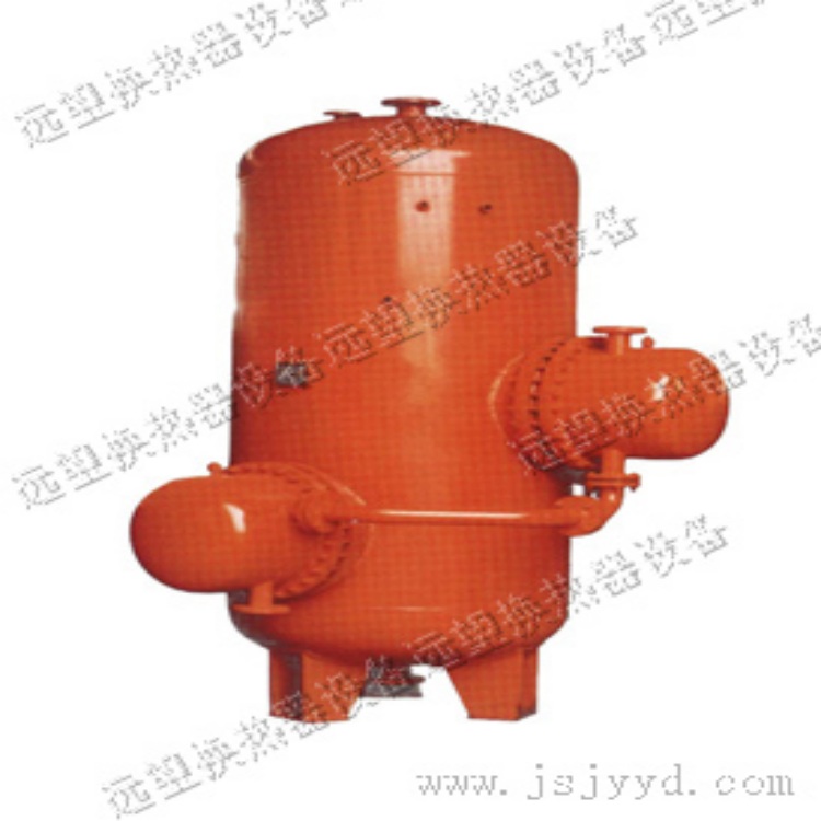 Volumetric heat exchanger
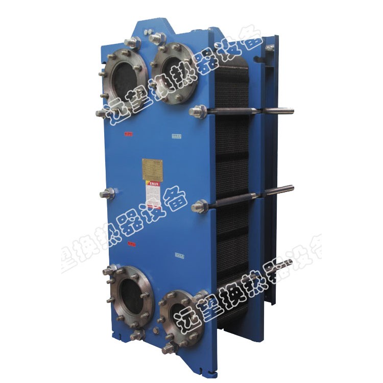 BR0.37 Series Plate Heat Exchangers
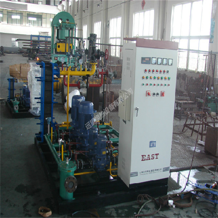
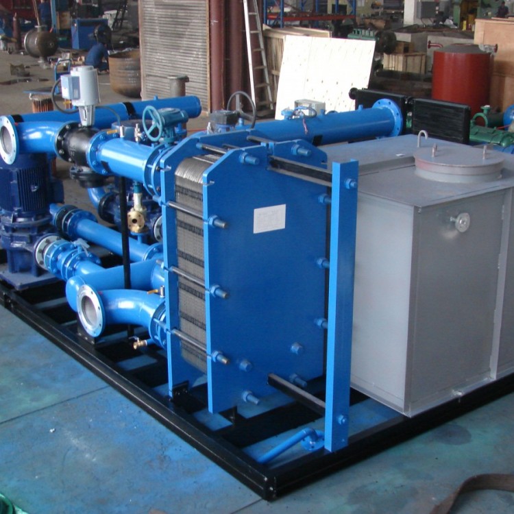
 Water-to-Water Intelligent Heat Exchange Unit
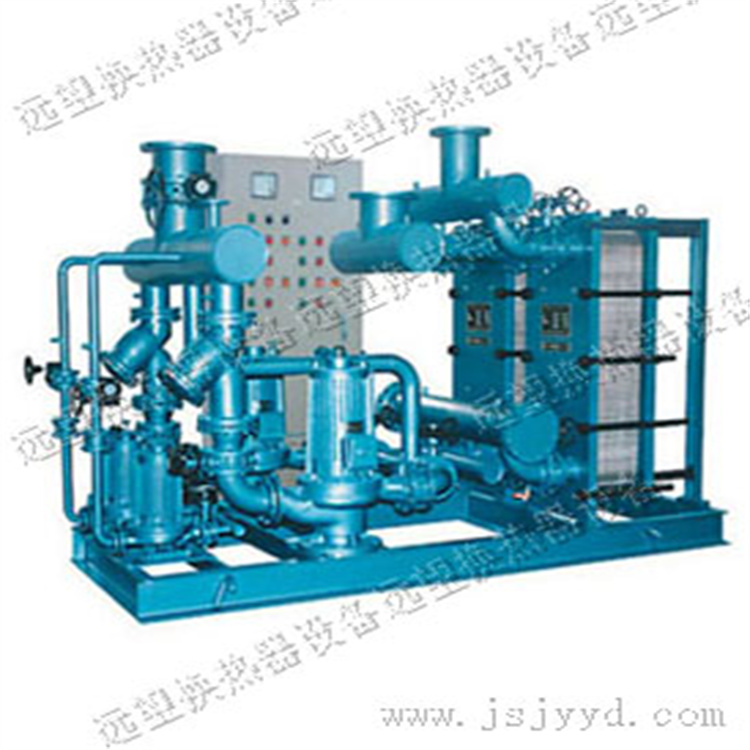
 High-efficiency Intelligent Plate Heat Exchanger Assembly
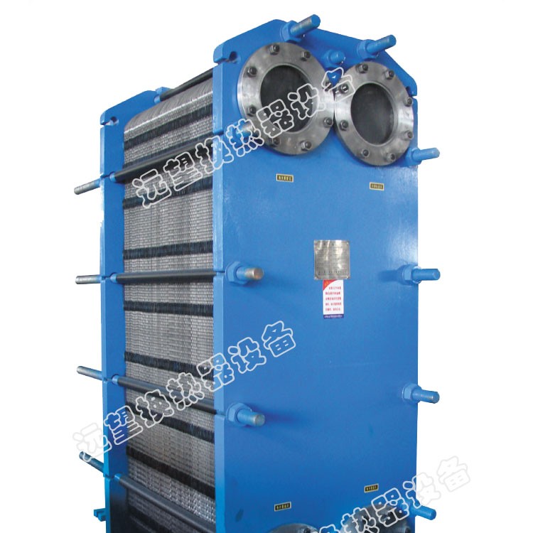 BR2.2 Plate Heat Exchanger
Product Details
Heat Exchangers, Chiller Units, Coolers, Plate Heat Exchangers, Heat Recovery...


产品Price 5000.00/Tai
最小起订Quantity:1 Tai 供货总Quantity: 50 Tai


Pressure |
|
Flow Rate |
0.5 to 1.0 m/s |
Sheet thickness |
1.2-0.8mm |
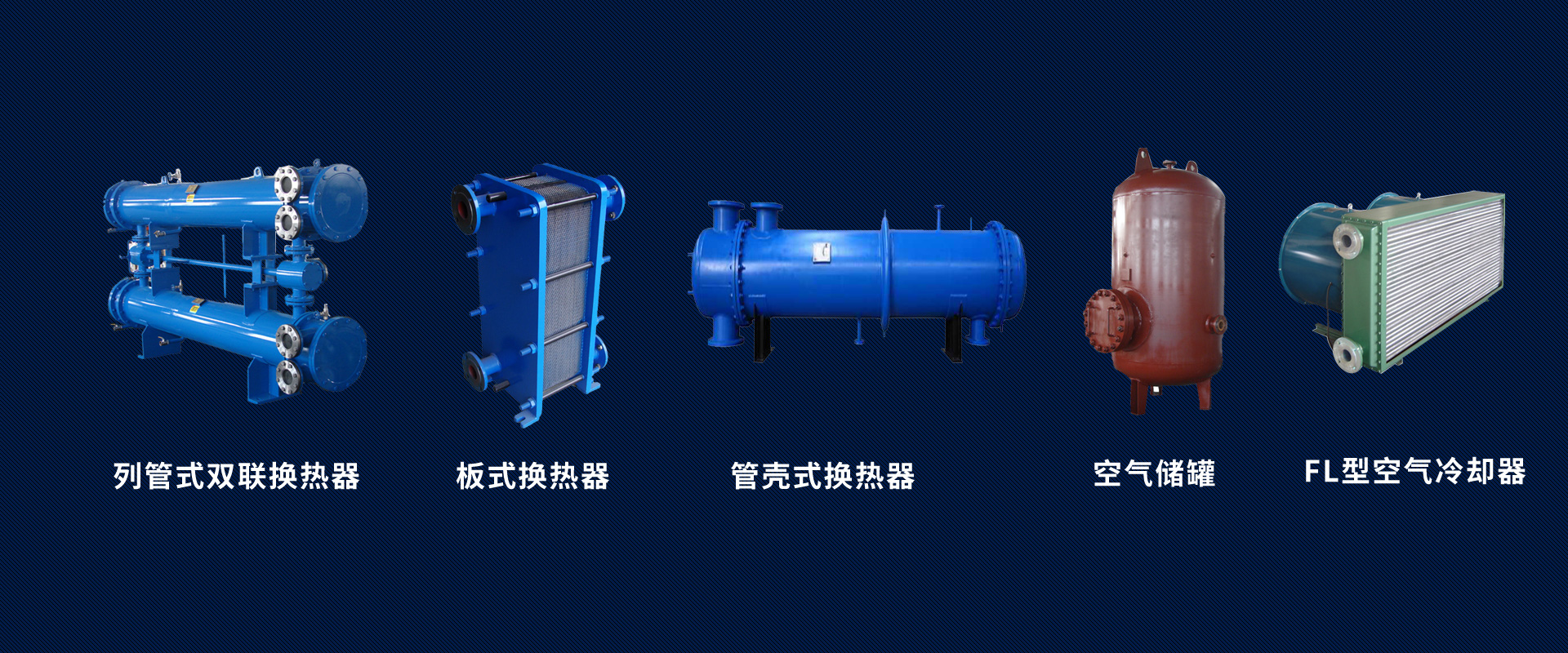
Shell and tube heat exchanger Shell and Tube Heat ExchangerAlso known as a tube-in-tube heat exchanger. It is a type of shell-and-tube heat exchanger where the wall surface of the tube bundle enclosed in the shell serves as the heat transfer surface. This heat exchanger has a simple structure, reliable operation, and can be manufactured from various structural materials (mainly metals), enabling its use under high temperature and pressure conditions. It is widely used currently. A pass through the tube bundle is called a tube pass; a pass through the shell is called a shell pass. The illustration shows a simple single-shell, single-tube pass heat exchanger, abbreviated as the 1-1 type heat exchanger. To increase the fluid velocity inside the tubes, baffles can be set up at both ends of the tube boxes, dividing all the tubes into several groups. This way, the fluid only passes through a portion of the tubes each time, thus making multiple passes through the tube bundle, which is referred to as multi-pass. Similarly, to increase the fluid velocity outside the tubes, longitudinal baffles can also be installed inside the shell, forcing the fluid to pass through the shell space multiple times, known as multi-shell pass. Multi-pass and multi-shell pass can be used in conjunction. ② Floating head heat exchanger - The tube sheet at one end of the tube bundle is freely floating, completely eliminating thermal stress; and the entire tube bundle can be pulled out from the shell, facilitating mechanical cleaning and maintenance. The floating head heat exchanger is widely used, but its structure is relatively complex and the cost is higher. 4.Shell and tube heat exchanger main control parameters
Shell-and-tube heat exchangers still dominate in chemical production worldwide. Although they may not be as efficient in heat transfer, compact in structure, or consume less metal as other new types of heat exchangers, they offer robust construction, high operational flexibility, strong adaptability, high reliability, a wide material selection, large processing capacity, and the ability to withstand high temperatures and pressures. Due to these features, they are still widely used in engineering projects.
2. Shell-and-tube heat exchanger structure
Composed of components such as the shell, heat transfer tube bundles, tube plates, baffle plates (shutters), and tube boxes. The shell is typically cylindrical, housing the tube bundles inside, with the ends of the bundles fixed to the tube plates. The two fluids, one cold and one hot, used for heat exchange flow either inside the tubes (tubular fluid) or outside them (shell fluid). To enhance the heat transfer coefficient of the fluid outside the tubes, baffles are usually installed inside the shell. These baffles increase the velocity of the shell fluid, forcing it to traverse the tube bundles multiple times laterally, thus enhancing turbulence. The heat exchange tubes can be arranged on the tube plates in an equilateral triangular or square pattern. The equilateral triangular arrangement is more compact, with higher turbulence and a greater heat transfer coefficient for the fluid outside the tubes; the square arrangement is easier to clean and suitable for fluids that tend to scale.
3. Shell-and-tube heat exchangers types
Due to the different temperatures of the fluid inside and outside the tubes, the shell and tube bundle of the heat exchanger also experience different temperatures. If the temperature difference is significant, a considerable thermal stress will be generated within the heat exchanger, leading to tube bending, fracturing, or being pulled off from the tube plates. Therefore, when the temperature difference between the tube bundle and the shell exceeds 50°C, appropriate compensation measures must be taken to eliminate or reduce the thermal stress. Depending on the type of compensation employed, shell-and-tube heat exchangers can be classified into the following main types:
① Fixed tube sheet heat exchangers have tube plates at both ends of the tube bundle integrated with the shell, featuring a simple structure. However, they are only suitable for heat exchange operations where the temperature difference between the cold and hot fluids is not significant and the shell side does not require mechanical cleaning. When the temperature difference is slightly greater and the shell side pressure is not too high, an elastic compensation ring can be installed on the shell to reduce thermal stress.
③ U-tube Heat Exchanger: Each heat exchange tube is bent into a U-shape, with both ends fixed at the upper and lower sections of the same tube plate. It is divided into two chambers, an inlet and an outlet, by the baffles inside the tube box. This type of heat exchanger completely eliminates thermal stress, has a simpler structure than the floating head type, but the tube side is not easy to clean.
Non-metallic Heat ExchangersIn chemical production, heat exchange of highly corrosive fluids requires the use of non-metallic materials such as ceramics, glass, F4, and graphite for shell-and-tube heat exchangers. These heat exchangers have poor heat exchange performance and are only suitable for low-pressure, low-vibration, and low-temperature conditions.
Shell and tube heat exchanger flow channel selection① For换热the cold and hot fluids, select the flow channels according to the following principles: ① Impure and scaling-prone fluids should flow through the tube side, as cleaning inside the tubes is more convenient; ② Corrosive fluids should flow through the tube side to prevent both the tube bundle and shell from being corroded simultaneously; ③ High-pressure fluids should flow through the tube side to avoid the shell bearing pressure; ④ Saturated steam should flow through the shell side, as the heat transfer coefficient of steam condensation is unrelated to the flow rate, and the condensate is easy to discharge; ⑤ If there is a significant temperature difference between the two fluids, when using a fixed tube plate heat exchanger, it is advisable to let the fluid with a higher heat transfer coefficient flow through the shell side to reduce thermal stress.
Operation EnhancementWhen there is a significant difference in the heat transfer coefficient on both sides of the tube wall (such as heat exchange between liquids with low viscosity and gases), it is necessary to reduce the thermal resistance on the side with a lower heat transfer coefficient. If the heat transfer coefficient outside the tube is low, an externally threaded tube (low finned tube) can be used to increase the heat transfer area on the outer side of the tube and enhance fluid turbulence, thereby reducing thermal resistance. If the heat transfer coefficient inside the tube is low, helical iron or spiral coils can be added inside the tube to increase turbulence and improve heat exchange. However, this will also increase the fluid flow resistance.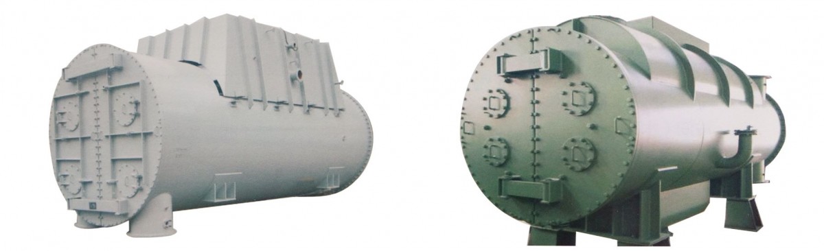
The main control parameters for shell-and-tube heat exchangers include heating area, hot water flow rate, heat exchange amount, and heat medium parameters.
2Key Selection Points
1) Based on the known flow rates of cold and hot fluids, initial and final temperatures, and specific heat capacity of the fluid, the required heat exchange area is determined. Initially estimate the heat exchange area by first assuming the heat transfer coefficient, determining the heat exchanger design, and then verifying the heat transfer coefficient K value.
2) When selecting a heat exchanger, pay attention to the pressure rating, operating temperature, and connection conditions of the interfaces. Under the premise of allowable pressure drop and installation conditions, choose a longer type with a smaller diameter for the tube-and-shell heat exchanger, which is beneficial for increasing the heat exchange capacity.
3) The pressure drop of the heat exchanger should not be too great, generally controlled between 0.01 and 0.05 MPa.
4) Flow rate should consider the fluid viscosity; for high viscosity fluids, the flow rate should be less than 0.5 to 1.0 m/s. Generally, the flow rate in fluid pipelines should be between 0.4 to 1.0 m/s; for fluids prone to scaling, a flow rate of 0.8 to 1.2 m/s is recommended.
5) It is advisable to install a filter before the high-temperature water enters the heat exchanger.
6) The individual processing and configuration combinations of heat exchangers in the heat exchange station should meet the total heating load and regulation requirements of the heat exchange station. Under the premise of meeting the user's heating load regulation requirements, the number of heat exchangers in the same heating coefficient should not be fewer than 2 and not more than 5.
5.Shell-and-tube heat exchanger construction and installation key points
1) Heat exchangers should be subjected to a hydrostatic test at 1.5 times the MAX working pressure, with the steam section not less than the steam supply pressure plus 0.3MPa; the hot water section should not be less than 0.4MPa. Under the test pressure, maintain a pressure that does not drop for 10 minutes.
2) The shell-and-tube heat exchanger should have sufficient space for removing the tube bundle at the front end, meaning the distance from its closure to the wall or roof should not be less than the length of the heat exchanger. The clear width of the equipment's operating passage should not be less than 0.8 meters.
3) The installation heights of various valves and instruments should be convenient for operation and observation.
4) The vertical clear distance from the highest point of the heater's upper attachment (usually the safety valve) to the lowest point of the building structure should meet the installation and inspection requirements and must not be less than 0.2m.
6.Shell-and-tube heat exchanger standard
1) Product Standards
Shell-and-tube Heat Exchanger GB151-1999
Flow-thru Type Volumetric Water Heaters and Semi-volumetric Water Heaters (U-shaped Tube Bundle) CJ/T 163-2002
2) Engineering Standards
"Code for Acceptance of Construction Quality of Water Supply, Drainage, and Heating Engineering - GB50242-2002"
3). Tube-and-shell heat exchanger standard drawings
05R103 Heat Exchange Station Engineering Design and Construction Drawings Set
01S122-1 to 10 Water Heater Selection and Installation
7. Shell-and-tube Heat Exchanger Manufacturer Introduction
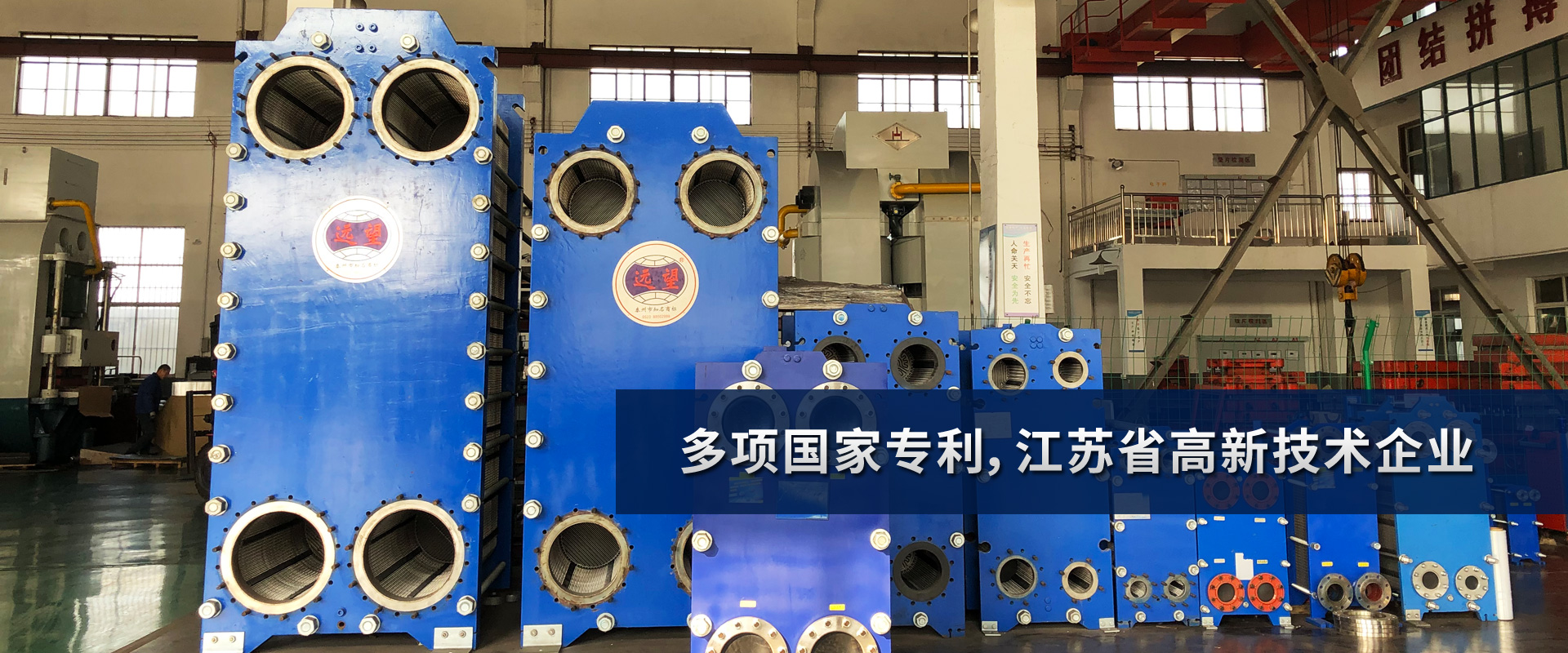
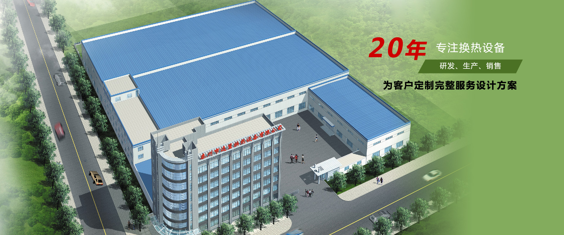
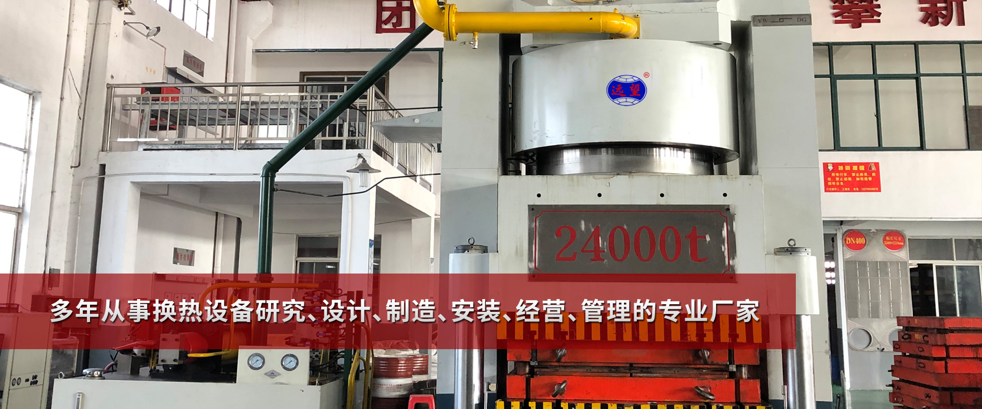
Cooling Tower ManufacturerYuanwang Heat Exchange Equipment Co., Ltd., a professional manufacturer of plate heat exchangers. Located in Jiangyan City, central Jiangsu Province. The company produces "Lengwei" brand plate heat exchangers and coolers. Main products:Plate Heat Exchanger,Cooler,Condenser,Diverting valve,Heat Exchanger Unit,Evaporative Condenser,Shell and tube heat exchanger,Bell and tube heat exchanger,Volumetric heat exchangerThe "Lingwei" brand is a well-known trademark in Jiangsu. The "Lingwei" brand coolers have passed the ISO9001 international quality system certification, strictly adhering to the standards of JB/T7356-94 for "Tubular Oil Coolers" and GB16409-96 for "Plate Heat Exchangers." Yuanwang coolers are reliable in quality and widely used. Yuanwang Heat Exchanger Equipment Co., Ltd. is a professional manufacturer and supplier of plate heat exchangers and coolers! Address: Advanced Industrial Zone, Louzhuang Town, Jiangyan City, Jiangsu Province
Phone: 0523-88691628, 88699968
Fax: 0523-88696288

Phone Consultation
QQ Service