

- AllProduct Category
-
Special Equipment
Powder Mixing / Liquid Stirring
Tank Accessories / Powder Conveyance
Eye Wash Station/Breathing Valve
Heat Exchangers/Filter
Blender/Sampler
Emergency Cooling Tower
Lubrication Equipment
Silencer
Water Chopper
Fire Retardant Device
Fiber Demister
Liquified Chlorine Vaporizer
Tornado Separator
Steam Temperature Reducer
Injector
Pipe Reactor
Gas Blender
Tubular Reactor
Blender


Recommended Products

详情描述
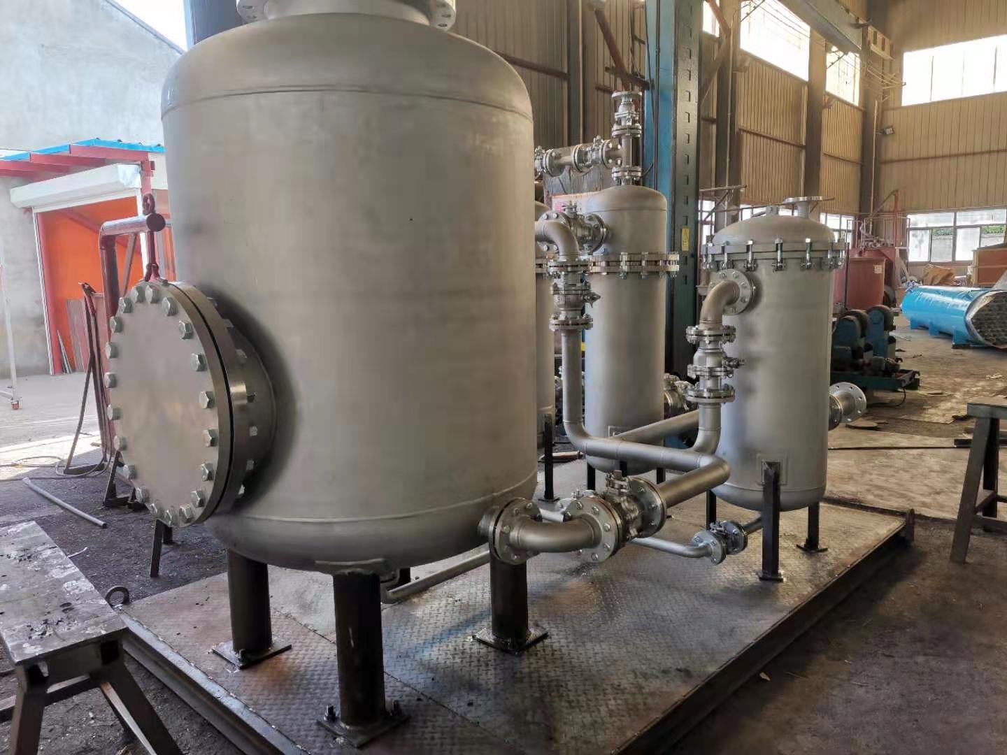
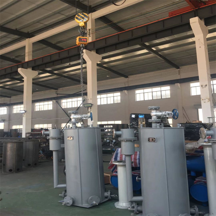
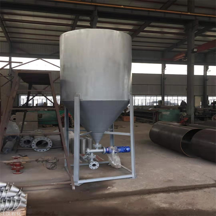
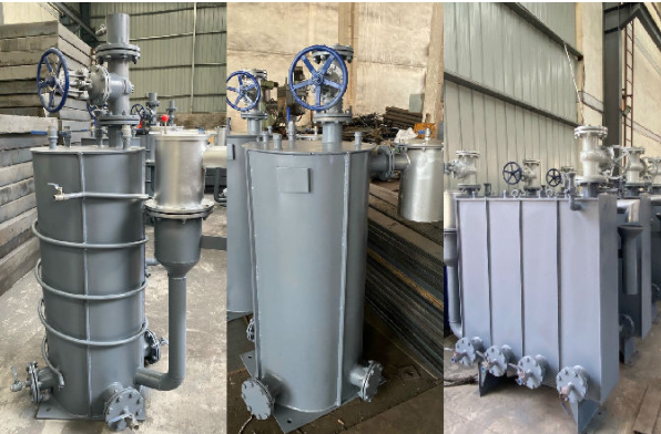
Gas drainage valves must be of the leak-proof type, with a condensate water outlet pipe diameter DN100 (PSQ-30-100), drainage pipe diameter DN100, water seal height: 3m, medium: converter gas condensate, structural form: vertical circular, equipped with overpressure protection and leak-proof device, design pressure: 0.05MPa, ensuring no gas leakage even if the water seal height inside the drainage valve is insufficient. The body material of the drainage valve is Q235-B, with a corrosion-resistant silicone rubber material used for the internal sealing ring. A gate valve (valve gate diameter consistent with the collection pipe diameter, model Z41H-16C, with complete flange gaskets and other sealing fasteners) must be fitted on the drainage collector pipe. Additionally, a sampling tube and ball valve (both with a diameter of DN15), model Q11F-16C, with complete flange gaskets and other sealing fasteners, are required. Each cavity of the drainage valve is equipped with a drain outlet and a manual access door, with a cast steel gate valve set on the drain outlet. A check valve and a cast steel gate valve (both with a nominal pressure of 1.6MPa) are installed on the drainage valve's make-up water pipe. The leak-proof device is made of stainless steel. The drainage valve must be equipped with a service ladder for valve operation.
2. After the drain valve is welded, apply kerosene and chalk to inspect the tightness of the weld seam. Non-leakage is considered acceptable; if leakage is detected, the weld must be chipped out and re-welded, followed by further inspection. Repeat this process until no leakage is present.
3. Upon completion of the drain valve, a tightness test should be conducted and a written inspection record should be issued. The test pressure for the drain valve should be carried out at 50kPa, with a hold time of 10 minutes; no leakage is considered passable.
4. All steel pipes, both inner and outer walls, and steel plate surfaces must be coated with two layers of epoxy asphalt anti-corrosion paint before assembly welding, with a film thickness of not less than 200μm. Additional painting is required after assembly welding is completed.
5. After equipment pressure testing is completed, apply two coats of anti-rust primer and two coats of topcoat. The color of the topcoat shall be in accordance with the color standard file provided by Party A.
6. Normal Service Life of Supply Equipment: 3-5 years or more.
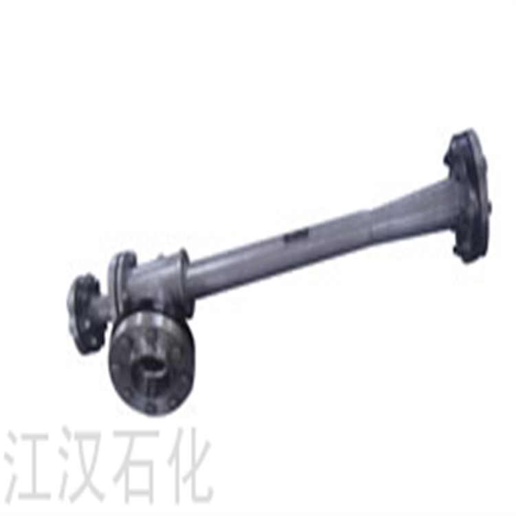
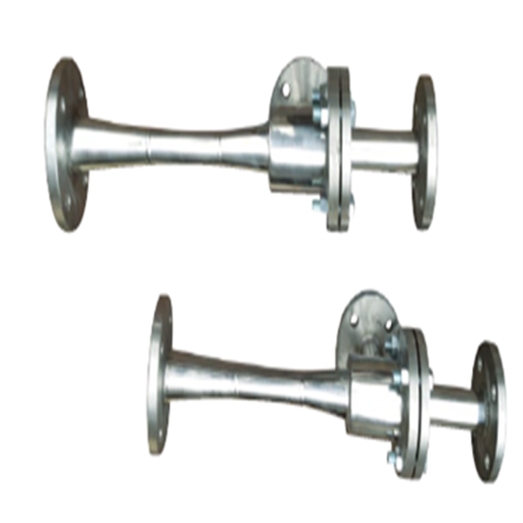
Structure and Working Principle of the New Gas Drainage Valve Leak Prevention Device
As shown in the figure, the new gas drainage device includes a body with an inlet and an outlet. A float capable of vertically moving up and down along a guide tube mounted inside the body is set within the interior of the body. A sealing washer for the outlet is installed on the float. The guide tube is mounted on the inner wall of the body and is slidable with the float; a special sealing washer with a spherical pad that fits the drainage pipeline is set at the bottom of the float. A feed pipe connected to the drainage device is mounted on the inlet. A drainage pipe is set on the outlet. A flange and a flange cover are mounted at the top of the body. A sealing washer is placed between the flange and the flange cover. The flange cover facilitates repair and installation.
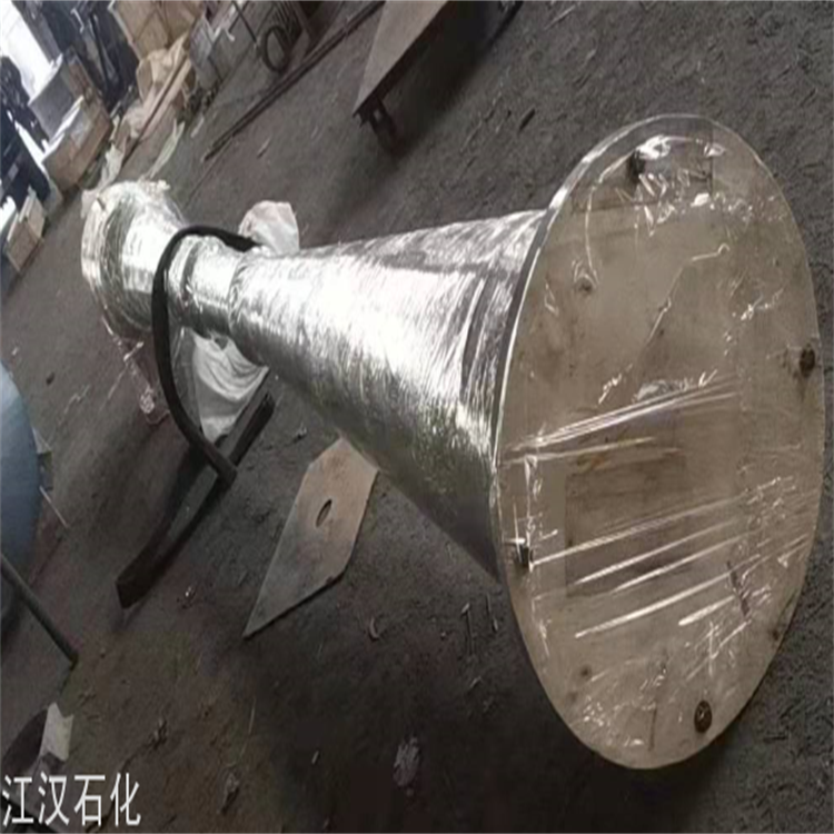
Illustration of the Structure of the New Leak Prevention Device
In use, as shown in the diagram, when the water level in the drain is normal, the float below the gas leak prevention device in the gas pipe drain is filled with water. The water separates the gas from the atmosphere. At this point, the gravity of the float is slightly greater than the buoyancy it experiences in the water. The seal of the float presses tightly against the drain opening. As the water level rises, the float rises and expels some condensate water until the gravity of the float exceeds the buoyancy. When the gas pressure exceeds the effective water seal height of the drain, the water seal of the drain is pierced. More water than normal will be expelled from the gas leak prevention device in the gas pipe drain. However, the gravity of the float is significantly greater than the buoyancy of the remaining water in the cylinder, causing the float to press tightly against the drain opening, thus preventing gas leaks.
询价单


