

- AllProduct Category
-
Special Equipment
Powder Mixing / Liquid Stirring
Tank Accessories / Powder Conveyance
Eye Wash Station/Breathing Valve
Heat Exchangers/Filter
Blender/Sampler
Emergency Cooling Tower
Lubrication Equipment
Silencer
Water Chopper
Fire Retardant Device
Fiber Demister
Liquified Chlorine Vaporizer
Tornado Separator
Steam Temperature Reducer
Injector
Pipe Reactor
Gas Blender
Tubular Reactor
Blender


Recommended Products

详情描述
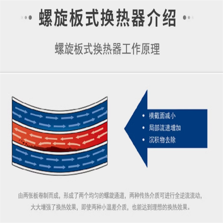
Basic Structure and Working Principle of Spiral Plate Heat Exchangers:
Spiral plate heat exchangers are formed by rolling two longer steel plates together. Equally spaced fixed-distance columns are welded between the plates to create a certain flow passage spacing. These columns also serve to support the steel plates against fluid pressure and to induce turbulence in the fluid flow, thereby enhancing the heat exchanger's efficiency. Adjacent flow channels carry two fluids of different temperatures, which are heated through the spiral heat exchange plates to achieve heat exchange. The spacing between the flow channels is determined based on the flow rate, and can be the same or different.
For the two media used in heat exchange, if both are liquids, they must flow in a counter-current manner within the helical plate heat exchanger. Counter-current refers to the two liquids in adjacent channels of heat exchange flowing in opposite directions along the helical channel. This ensures a constant temperature difference between the two fluid media, thereby achieving the desired heat transfer effect.
For the two mediums used in heat exchange, one is liquid and the other is gas. They must flow in a crossflow manner within the spiral plate heat exchanger, meaning the liquid flows along the spiral direction within the exchanger, while the gas flows directly through the axial direction of the exchanger. This is primarily due to the characteristics of gas, which generally requires high flow rates and low resistance, or some are used for steam condensation. Therefore, gas is usually not allowed to flow in the spiral direction.
Spiral Plate Heat Exchanger Types:
Non-detachable
The spiral plate heat exchangers, after rolling, are sealed at both ends and are not removable, forming a fixed structure with the internal channels inaccessible. They are suitable for fluid heat exchange that is not prone to clogging. The non-detachable types are further divided into horizontal and vertical structures.
2. Detachable
After rolling, the spiral plate heat exchanger has only one channel sealed at each end, while the other channel remains open. A flange is then added to the end face for sealing, which can be removed for cleaning the internal channel. It is suitable for heat exchange of fluids prone to clogging.
3. Special Forms:
Some spiral plate heat exchangers used in the chemical industry require special structures due to the processing requirements, featuring flanged ends, end caps, or even two heat exchangers connected in series. The structures vary, and our design department will design them according to the actual requirements of the customers.
The main heat exchange materials of the spiral plate heat exchanger are primarily divided into carbon steel and stainless steel. The spiral plate material for carbon steel is Q235-A or Q235-B; the main spiral plate materials for stainless steel are 0Cr18Ni9 (304) and 00Cr17Ni14Mo2 (316L).
Spiral plate heat exchanger selection and calculation:
1. Heat Load: Q = qv1ρ1Cp1(T1 - T2) / 3.6 = qv2ρ2Cp2(t2 - t1) / 3.6
Q—Thermal Load, Unit: W (1 Kcal/h = 1.163 W)
Cp1 – Specific heat capacity of hot medium, unit: KJ/Kg℃
Cp2 - Specific heat capacity of the cold medium, unit: KJ/Kg℃
qv1 — Hot medium flow rate, unit: m³/h.
qv2—Flow rate of cold medium, unit: m³/h
T1 — Import temperature of hot medium, unit: ℃
T2 – Outlet temperature of hot medium, unit: ℃
ρ1 — Density of the hot medium, unit: Kg/m³
ρ2 - Density of cold medium, unit: Kg/m³
t1 — Imported temperature of cold medium, unit: ℃
t2 — Export temperature of cold medium, unit: ℃
Logarithmic mean temperature difference: (Unit: ℃) Δtm = (T1 - t2) - (T2 - t1) / ln[(T1 - t2) / (T2 - t1)]
When the temperature difference between the hot medium's inlet and outlet is equal to the temperature difference between the cold medium's inlet and outlet, use the arithmetic mean temperature difference: (Unit: ℃) Δtam = (T1 + T2) - (t1 + t2) / 2
3. Heat Exchange Area: F = uQ / (KΔtm)
F—Heat exchange area of spiral plate heat exchangers, unit: m².
u—Soiling Coefficient, 1.1-1.2
K—Overall thermal conductivity, unit: W/m2℃; the K value can be selected from the following: Water-Water, Water-Vapor: 1500-2000; Oil-Water, Oil-Vapor: 300-600; Water-Organic Vapor: 500-1000; Water-Smoke, Water-Air: 30-100.
4. Heat exchanger flow channel medium velocity: Vb1 = qv1 / (3600 * A1) Vb2 = qv2 / (3600 * A2)
Vb1 – Flow velocity of the heat transfer medium within the heat exchanger, unit: m/s.
Vb2 — Flow velocity of the heat medium within the heat exchange flow, unit: m/s.
A1: Cross-sectional area of the heat medium heat exchange channel, unit: m², A1 = 0.9Bb1, where: B is the width of the spiral heat exchange plate, b1 is the spacing width of the heat medium heat exchange channel, unit: m.
A2: Cross-sectional area of the cold medium heat exchange channel, unit: m², A2 = 0.9Bb2, where B is the width of the spiral heat exchange plate, b2 is the spacing width of the cold medium heat exchange channel, unit: m.
The fluid velocity inside the spiral plate heat exchanger, for liquids, is 0.8-2 m/s, and for gases, it is 5-15 m/s.
Performance and Model Representation Method:
1. Design temperature range for spiral plate heat exchangers:
a) The design temperature range for the non-separable helical plate heat exchanger is determined based on the allowable service temperature of the steel.
b) The design temperature range for the removable spiral plate heat exchanger is determined by the allowable service temperature of the gaskets.
2. General spiral plate heat exchangers are designed for a working pressure of PN ≤ 2.5 MPa.
询价单


