


- AllProduct Category
-
Submersible Pump
Self-Priming Pump
Axial Flow Pump
Chemical Pumps
Mixed Flow Pump
Magnetic Pump
Desulfurization Pump
Screw Pump
Press Filter Pump
Slurry Pump
Multi-Stage Pump
Vortex Pump


详情描述
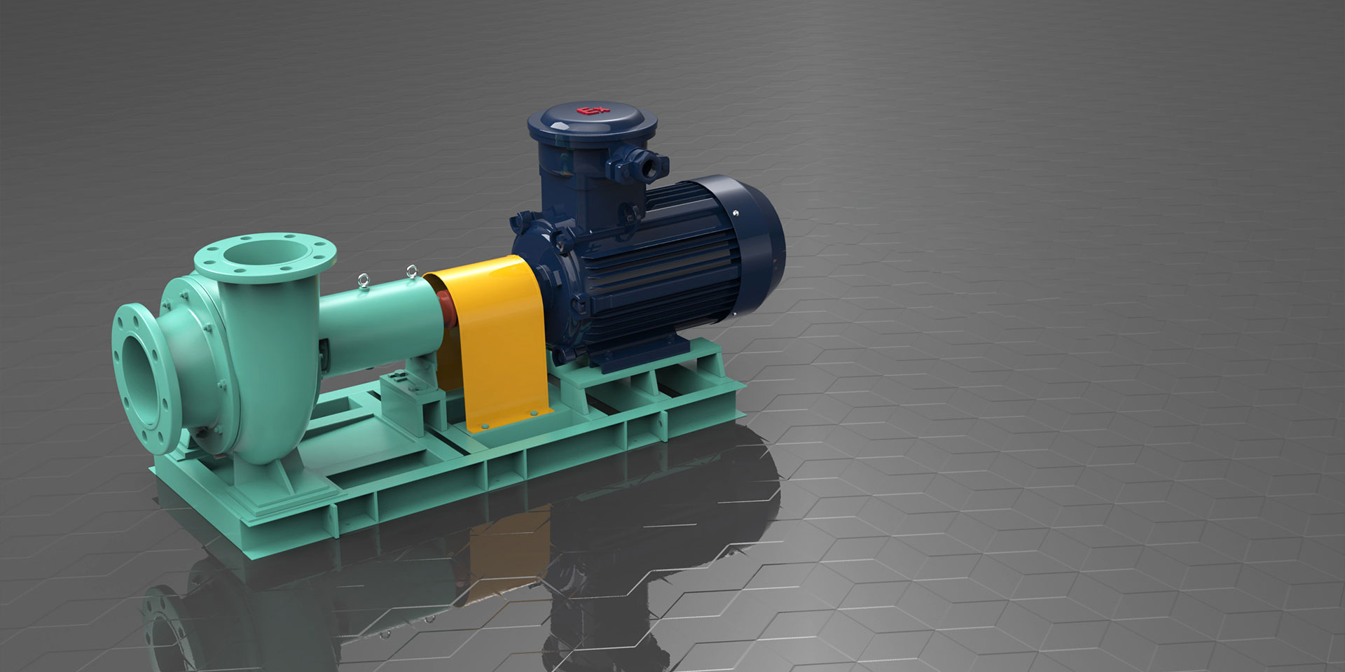
I. Overview of HLC Submersible Long Shaft Pumps
The HLC vertical long shaft pump is an advanced and mature product series developed based on the absorption of advanced design and manufacturing experiences from both home and abroad, combined with market demands. It is suitable for transporting wastewater containing clean water and certain solid particles (such as iron filings, sand particles, coal powder, etc.), corrosive industrial wastewater, seawater; the temperature of the liquid being transported should not exceed 80°C. It is widely used in original water treatment plants, sewage treatment plants, metallurgical and steel industry (especially for transporting iron oxide scale in the industry's vortex pool), power plants, mines, municipal engineering, and irrigation and water conservancy projects in farmlands.
Section II: Significance of HLC Model
Model Significance
300HLC2-50A
300mm pump outlet diameter φ300mm
HLC — Vertical Long Axle Pump
2 - Blade impeller stage: 2 stages (omitted when stage is 1)
50- Design head is 50m
A—Impeller Outer Diameter Cutting Code
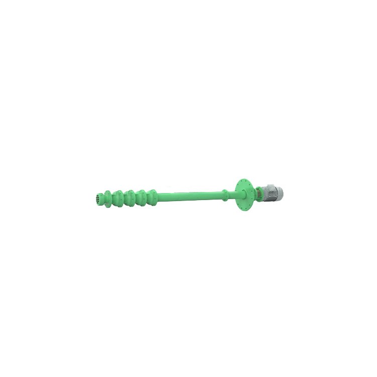
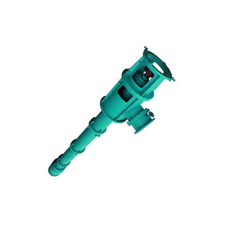
III. Structural Features of HLC Long Axial Multi-Stage Submersible Pumps
The HLC vertical long shaft pump has an inlet that is vertically downward and an outlet that is horizontal. It is installed on a single foundation and is directly coupled with the motor. Looking down from the motor end, the pump rotates in a counterclockwise direction. Its main features include:
1. Optimized design with hydraulic design software, offering superior performance. It also fully considers the erosion resistance of the impeller and guide vanes, significantly extending the lifespan of wear-prone components like the impeller. The product operates smoothly, is safe and reliable, and highly energy-efficient.
2. The pump inlet is equipped with a filter screen, featuring appropriately sized openings. This effectively prevents large particles from entering the pump and damaging it, while also ensuring that the net water intake area is over 3.5 times the cross-sectional area of the discharge pipe, significantly reducing inlet losses and improving pump efficiency.
3. The impeller is balanced by balancing holes to counteract the axial force, and both the front and rear covers of the impeller are equipped with replaceable sealing rings to protect the impeller and pump body. The sealing rings feature a special weir-type structure, which effectively prevents the sedimentation of iron oxide scale or other impurities into the gap of the sealing ring after the pump stops, significantly extending the service life of the sealing rings and impeller.
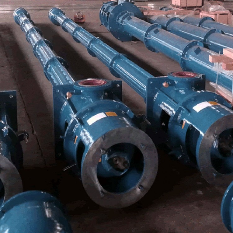
4. The pump's intermediate shaft, suction pipe, and guard tube are segmented. The intermediate shaft uses sleeve coupling technology, which improves radial coaxiality tenfold compared to other coupling methods, reducing the overall vibration by over 70%. The number of suction pipes can be increased or decreased according to customer requirements, accommodating different submersion depths. The impeller and guide vane body can be multi-stage, meeting various lift requirements.
5. The pump's suction pipe is connected by flanges with a guide bearing in the middle. The pump guide bearing is made of reinforced filled PTFE or Canada's Super Dragon bearings, and can also use nitrile rubber (for medium temperatures above 55℃). The shaft is protected by a casing. When conveying clean water, the casing can be removed, and the guide bearing does not require cooling and lubricating water. When conveying wastewater, the guide bearing must be externally connected to cooling and lubricating water. In areas where there is no clean water or the cost of clean water is high, a special structure can be added. The medium transported by the pump is filtered or sediment-separated before cooling and lubricating the guide bearing. The lubricating water system can be equipped with flow and pressure relays, and other control elements. If the water supply before startup is below the rated supply, the pump cannot start. If water is lost or pressure drops during operation due to some reason (pipeline blockage), the relay will send an alarm signal, the control room buzzer will sound, the red light will alarm. At this time, the valve of the bypass system can be opened to supply water, ensuring sufficient water supply, and at the same time, the fault can be repaired. This control system can achieve remote control.
6. The residual axial force of the pump and the weight of the rotor components are supported by the thrust bearing within the motor base or by the motor equipped with a thrust bearing. The thrust bearing is lubricated with light oil and externally cooled with water. Temperature control elements can be installed in the thrust bearing.
7. The pump shaft seal is a packing seal, and replaceable shaft sleeves are installed at the shaft seal and guide bearing to protect the shaft. The axial position of the impeller can be easily adjusted by the top of the bearing component or an adjusting nut within the pump coupling.
8. Pumps can be equipped with a control cabinet that offers various functions such as automatic start/stop based on liquid level, overload alarms, and real-time remote monitoring, enabling centralized control of multiple pumps via network. Pumps with an aperture larger than 500mm are equipped with an automatic air release system.
Section 4: HLC Performance Parameters Table
| Parameters | Traffic | Flow Rate | RPM | Axial Power | Motor | Efficiency. | Pump weight | ||
| Model Type | Power | Model | |||||||
| m3/h | l/s | m | rpm | kw | kw | % | kg | ||
| 150HLC-23 | 75 | 20.83 | 27.5 | 2980 | 7.8 | 18.5 | Y160L-2 | 72 | 610+100N |
| 150 | 41.67 | 23 | 12.4 | 76 | |||||
| 190 | 52.78 | 16.5 | 11.7 | 73 | |||||
| 150HLC-30 | 75 | 20.83 | 36 | 2980 | 10.22 | 22 | Y180M-2 | 72 | 620+100N |
| 150 | 41.67 | 30 | 16.35 | 75 | |||||
| 190 | 52.78 | 24 | 17.5 | 71 | |||||
| 150HLC2-46 | 75 | 20.83 | 55 | 2980 | 15.61 | 37 | Y200L2-2 | 72 | 645+100N |
| 150 | 41.67 | 46 | 24.74 | 76 | |||||
| 190 | 52.78 | 33 | 23.41 | 73 | |||||
| 150HLC2-60 | 75 | 20.83 | 72 | 2980 | 20.4 | 45 | Y225M-2 | 72 | 660+100N |
| 150 | 41.67 | 60 | 32.7 | 75 | |||||
| 190 | 52.78 | 48 | 35 | 71 | |||||
| 150HLC3-90 | 75 | 20.83 | 108 | 2980 | 30.7 | 75 | Y280S-2 | 72 | 700+100N |
| 150 | 41.67 | 90 | 49.1 | 75 | |||||
| 190 | 52.78 | 72 | 52.5 | 71 | |||||
| 200HLC-19 | 190 | 52.78 | 22 | 1480 | 15.6 | 30 | Y200L-4 | 73 | 900+170N |
| 300 | 83.33 | 19 | 20.2 | 77 | |||||
| 360 | 100 | 15.8 | 21.5 | 72 | |||||
| 200HLC-23 | 190 | 52.78 | 26.8 | 1480 | 19 | 37 | Y225S-4 | 73 | 900+170N |
| 300 | 83.33 | 23 | 24.4 | 77 | |||||
| 360 | 100 | 20.2 | 27.2 | 73 | |||||
| 200HLC2-38 | 190 | 52.78 | 44 | 1480 | 31.2 | 55 | Y250M-4 | 73 | 1020+170N |
| 300 | 83.33 | 38 | 40.3 | 77 | |||||
| 360 | 100 | 31.6 | 43.1 | 72 | |||||
| 200HLC2-46 | 190 | 52.78 | 53.6 | 1480 | 38 | 75 | Y280S-4 | 73 | 1020+170N |
| 300 | 83.33 | 46 | 48.8 | 77 | |||||
| 360 | 100 | 40.4 | 54.4 | 73 | |||||
| 200HLC3-57 | 190 | 52.78 | 66 | 1480 | 46.8 | 75 | Y280S-4 | 73 | 1140+170N |
| 300 | 83.33 | 57 | 60.5 | 77 | |||||
| 360 | 100 | 47.4 | 64.6 | 72 | |||||
| 200HLC3-69 | 190 | 52.78 | 80.4 | 1480 | 57 | 110 | Y315S-4 | 73 | 1140+170N |
| 300 | 83.33 | 69 | 73.2 | 77 | |||||
| 360 | 100 | 60.6 | 81.6 | 73 | |||||
| 200HLC4-92 | 190 | 52.78 | 107.2 | 1480 | 76 | 132 | Y315M-4 | 73 | 1260+170N |
| 300 | 83.33 | 92 | 97.6 | 77 | |||||
| 360 | 100 | 80.8 | 108.8 | 73 | |||||
| 250HLC-20 | 360 | 100 | 22.8 | 1480 | 30.2 | 45 | Y225M-4 | 74 | 1200+250N |
| 480 | 133.3 | 19.8 | 32.8 | 79 | |||||
| 540 | 150 | 17.8 | 34.9 | 75 | |||||
| 250HLC-32 | 360 | 100 | 35.5 | 1480 | 47.1 | 75 | Y280S-4 | 74 | 1280+250N |
| 480 | 133.3 | 31.5 | 52.5 | 78.5 | |||||
| 540 | 150 | 29.1 | 58.7 | 73 | |||||
| 250HLC2-40 | 360 | 100 | 45.6 | 1480 | 60.5 | 90 | Y280M-4 | 74 | 1400+250N |
| 480 | 133.3 | 39.6 | 65.6 | 79 | |||||
| 540 | 150 | 35.6 | 69.9 | 75 | |||||
| 250HLC2-63 | 360 | 100 | 71 | 1480 | 94.2 | 160 | Y315L1-4 | 74 | 1500+250N |
| 480 | 133.3 | 63 | 105 | 78.5 | |||||
| 540 | 150 | 58.2 | 117.3 | 73 | |||||
| 250HLC3-95 | 360 | 100 | 106.5 | 1480 | 141.2 | 220 | Y315M1-4 | 74 | 1720+250N |
| 480 | 133.3 | 94.5 | 157.4 | 78.5 | |||||
| 540 | 150 | 87.3 | 176 | 73 | |||||
| 300HLC-25 | 540 | 150 | 27.5 | 1480 | 54.7 | 75 | Y208S-4 | 74 | 1340+270N |
| 660 | 183.3 | 25 | 56.6 | 79.5 | |||||
| 750 | 208.3 | 21.6 | 58.9 | 75 | |||||
| Parameters | Traffic | Head pump capacity | RPM (Revolutions Per Minute) | Axial Power | Motor | Efficiency | Pump weight | ||
| Date | Capacity | Head | Speed | Shaft | Eff. | Weight | |||
| Q | H | n | power | ||||||
| Model | Pa | Power | Model | ||||||
| Type | Power | Type | |||||||
| P | |||||||||
| m3/h | l/s | m | rpm | kw | kw | % | kg | ||
| 300HLC-39 | 540 | 150 | 43 | 1480 | 85.5 | 132 | Y315M-4 | 74 | 1480+270N |
| 660 | 183.3 | 39 | 88.8 | 79 | |||||
| 750 | 208.3 | 35.6 | 97 | 75 | |||||
| 300HLC2-50 | 540 | 150 | 55 | 1480 | 109.4 | 160 | Y315L1-4 | 74 | 1580+270N |
| 660 | 183.3 | 50 | 113.1 | 79.5 | |||||
| 750 | 208.3 | 43.2 | 117.7 | 75 | |||||
| 300HLC2-78 | 540 | 150 | 86 | 1480 | 171 | 250 | Y355M2-4 | 74 | 1780+270N |
| 660 | 183.3 | 78 | 177.6 | 79 | |||||
| 750 | 208.3 | 71.2 | 194 | 75 | |||||
| 350HLC-19 | 750 | 208.3 | 22.2 | 1480 | 60.5 | 90 | Y280M-4 | 75 | 1540+270N |
| 900 | 250 | 19.3 | 58.4 | 81 | |||||
| 1050 | 291.7 | 16.1 | 60.6 | 76 | |||||
| 350HLC-30 | 750 | 208.3 | 33.5 | 1480 | 90.1 | 132 | Y315M-4 | 76 | 1650+320N |
| 900 | 250 | 30.2 | 92 | 80.5 | |||||
| 1050 | 291.7 | 25.5 | 98.6 | 74 | |||||
| 350HLC-48 | 750 | 208.3 | 51.8 | 1480 | 143.1 | 200 | Y315L2-4 | 74 | 1750+320N |
| 900 | 250 | 47.9 | 146.8 | 80 | |||||
| 1050 | 291.7 | 42.5 | 162.1 | 75 | |||||
| 350HLC2-60 | 750 | 208.3 | 67 | 1480 | 180.2 | 250 | Y315M2-4 | 76 | 1920+320N |
| 900 | 250 | 60.4 | 184 | 80.5 | |||||
| 1050 | 291.7 | 51 | 197.2 | 74 | |||||
| 400HLC-25 | 1050 | 291.7 | 28.3 | 1480 | 106.6 | 160 | Y315L1-4 | 76 | 2170+380N |
| 1320 | 366.7 | 25 | 109.7 | 82 | |||||
| 1500 | 416.7 | 22 | 116.8 | 77 | |||||
| 400HLC-39 | 1050 | 291.7 | 44.3 | 1480 | 169 | 250 | Y355M2-4 | 75 | 2280+380N |
| 1320 | 366.7 | 39 | 172.1 | 81.5 | |||||
| 1500 | 416.7 | 34.3 | 186.9 | 75 | |||||
| 400HLC2-50 | 1050 | 291.7 | 56.6 | 1480 | 213.1 | 315 | Y355L2-4 | 76 | 2520+380N |
| 1320 | 366.7 | 50 | 219.3 | 82 | |||||
| 1500 | 416.7 | 44 | 233.6 | 77 | |||||
| 400HLC-62 | 1050 | 291.7 | 68.5 | 1480 | 257.9 | 355 | YLS4001-4 | 76 | 2650+400N |
| 1320 | 366.7 | 61.9 | 274.9 | 81 | |||||
| 1500 | 416.7 | 56.6 | 308.5 | 75 | |||||
| 450HLC-17 | 1500 | 416.7 | 19.7 | 980 | 104.6 | 132 | Y315L1-6 | 77 | 2540+450N |
| 1740 | 483.3 | 17.4 | 98.8 | 83.5 | |||||
| 1920 | 533.3 | 15.7 | 108.1 | 76 | |||||
| 450HLC-27 | 1500 | 416.7 | 29.8 | 980 | 162.4 | 220 | Y355L1-6 | 75 | 2650+500N |
| 1740 | 483.3 | 27.2 | 155.4 | 83 | |||||
| 1920 | 533.3 | 25 | 169.9 | 77 | |||||
| 450HLC-43 | 1500 | 416.7 | 46.2 | 980 | 245.3 | 315 | YLS4003-6 | 77 | 2800+500N |
| 1740 | 483.3 | 43.1 | 249.2 | 82 | |||||
| 1920 | 533.3 | 40.5 | 278.8 | 76 | |||||
| 450HLC2-54 | 1500 | 416.7 | 59.6 | 980 | 324.8 | 400 | YLS4005-6 | 75 | 3100+500N |
| 1740 | 483.3 | 54.4 | 310.8 | 83 | |||||
| 1920 | 533.3 | 50 | 339.7 | 77 | |||||
| 500HLC-20 | 1920 | 533.3 | 21 | 980 | 137.3 | 200 | Y355M3-6 | 80 | 3600+900N |
| 2160 | 600 | 20 | 139.3 | 84.5 | |||||
| 2400 | 666.7 | 17.8 | 147.4 | 79 | |||||
| 500HLC-31 | 1920 | 533.3 | 34 | 980 | 222.4 | 280 | YLS4002-6 | 80 | 4000+900N |
| 2160 | 600 | 31.4 | 220 | 84 | |||||
| 2400 | 666.7 | 28.5 | 235.9 | 79 | |||||
| 500HLC-50 | 1920 | 533.3 | 52.8 | 980 | 347.5 | 450 | YLS4501-6 | 79.5 | 4300+900N |
| 2160 | 600 | 49.8 | 353.2 | 83 | |||||
| 2400 | 666.7 | 46.1 | 386.5 | 77 | |||||
| Parameters | Traffic | Head pump discharge | RPM | Shaft Power | Motor | Efficiency | Pump weight | ||
| Date | Capacity | Head | Speed | Shaft | Eff. | Weight | |||
| Q | H | n | power | ||||||
| Model | Pa | Power | Model | ||||||
| Type | Power | Type | |||||||
| P | |||||||||
| m3/h | l/s | m | rpm | kw | kw | % | kg | ||
| 500HLC2-63 | 1920 | 533.3 | 68 | 980 | 444.7 | 560 | YLS4503-6 | 80 | 4600+900N |
| 2160 | 600 | 62.8 | 440.1 | 84 | |||||
| 2400 | 666.7 | 57 | 471.9 | 79 | |||||
| 600HLC-25 | 2400 | 666.7 | 29.7 | 980 | 239.8 | 315 | YLS4003-6 | 81 | 4800+1060N |
| 3000 | 833.3 | 25 | 238.8 | 85.6 | |||||
| 3420 | 950 | 21.6 | 245.5 | 82 | |||||
| 600HLC-39 | 2400 | 666.7 | 43.9 | 980 | 354.5 | 450 | YLS4501-6 | 81 | 5340+1060N |
| 3000 | 833.3 | 39 | 375.1 | 85 | |||||
| 3420 | 950 | 34.3 | 389.8 | 82 | |||||
| 600HLC-62 | 2400 | 666.7 | 68.2 | 980 | 550.1 | 710 | YLS5001-6 | 81 | 5340+1060N |
| 3000 | 833.3 | 62 | 599.2 | 84.5 | |||||
| 3420 | 950 | 56.7 | 651.7 | 81 | |||||
| 700HLC-20 | 3420 | 950 | 22.6 | 742 | 253.5 | 315 | YLS4501-8 | 83 | 5230+1200N |
| 3900 | 1083.3 | 20.3 | 252.1 | 85.5 | |||||
| 4380 | 1216.7 | 17.9 | 254.1 | 84 | |||||
| 700HLC-32 | 3420 | 950 | 33.4 | 742 | 388.7 | 450 | YLS4505-8 | 80 | 5440+1200N |
| 3900 | 1083.3 | 31.7 | 400.6 | 84 | |||||
| 4380 | 1216.7 | 27.3 | 401.9 | 81 | |||||
| 700HLC-50 | 3420 | 950 | 53.6 | 742 | 623.8 | 800 | YLS5601-8 | 80 | 5760+1200N |
| 3900 | 1083.3 | 50.3 | 635.7 | 84 | |||||
| 4380 | 1216.7 | 46.3 | 681.6 | 81 | |||||
| 800HLC-24 | 4380 | 1216.7 | 27.4 | 742 | 398.4 | 500 | YLS5001-8 | 82 | 6120+1380N |
| 5100 | 1416.7 | 24.3 | 401.6 | 84 | |||||
| 5600 | 1555.6 | 22 | 419.2 | 80 | |||||
| 800HLC-38 | 4380 | 1216.7 | 41.4 | 742 | 602 | 710 | YLS5004-8 | 82 | 6340+1380N |
| 5100 | 1416.7 | 37.9 | 626.4 | 84 | |||||
| 5600 | 1555.6 | 34.8 | 663.2 | 80 | |||||
| 800HLC-60 | 4380 | 1216.7 | 64.8 | 742 | 953.9 | 1120 | YLS6301-8 | 81 | 6670+1380N |
| 5100 | 1416.7 | 60.2 | 995 | 84 | |||||
| 5600 | 1555.6 | 56.7 | 1054.1 | 82 | |||||
| 900HLC-21 | 5600 | 1555.6 | 22.9 | 590 | 425.7 | 500 | YLS5003-10 | 82 | 7120+1630N |
| 6300 | 1750 | 20.8 | 424.7 | 84 | |||||
| 7000 | 1944.4 | 18.6 | 443 | 80 | |||||
| 900HLC-33 | 5600 | 1555.6 | 35.1 | 590 | 652.6 | 800 | YLS6302-10 | 82 | 7410+1630N |
| 6300 | 1750 | 32.6 | 665.6 | 84 | |||||
| 7000 | 1944.4 | 29.7 | 707.4 | 80 | |||||
| 900HLC-52 | 5600 | 1555.6 | 56.7 | 590 | 1073.8 | 1250 | YLS6303-10 | 80.5 | 7820+1630N |
| 6300 | 1750 | 51.7 | 1081.3 | 82 | |||||
| 7000 | 1944.4 | 48.3 | 1180 | 78 | |||||
| 1000HLC-25 | 7000 | 1944.4 | 28.7 | 590 | 667.6 | 800 | YLS5602-10 | 82 | 8240+1950N |
| 8400 | 2333.3 | 25.2 | 678.6 | 85 | |||||
| 9400 | 2611.1 | 22.4 | 708.4 | 81 | |||||
| 1000HLC-39 | 7000 | 1944.4 | 43.7 | 590 | 1029.1 | 1250 | YLS6303-10 | 81 | 8510+1950N |
| 8400 | 2333.3 | 39.4 | 1061 | 85 | |||||
| 9400 | 2611.1 | 35.1 | 1112.1 | 82 | |||||
| 1000HLC-63 | 7000 | 1944.4 | 68.2 | 590 | 1606 | 2000 | YL2000-10 /1703-1 | 81 | 8920+1950N |
| 8400 | 2333.3 | 62.6 | 1705.8 | 84 | |||||
| 9400 | 2611.1 | 58.1 | 1860.3 | 80 | |||||
| 1000HLC-63A | 6650 | 1847.2 | 61.6 | 590 | 1395.3 | 2000 | YL2000-10 /1703-1 | 80 | 8920+1950N |
| 7980 | 2216.7 | 56.5 | 1480.3 | 83 | |||||
| 8930 | 2480.1 | 52.4 | 1593.6 | 80 | |||||
| Note: N represents the number of riser pipe sections. | |||||||||


