
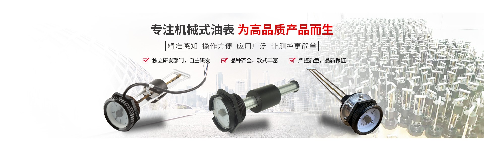


The mechanical oil gauge is a traditional gauge that senses the oil level within the fuel tank through an oil float and a pull string, which then reflects the oil level to the dashboard. The mechanical oil gauge operates without power and can be customized to include high and low level alarm functions according to customer requirements.
The primary function of the mechanical oil gauge:
1. This product combines liquid level detection and display in one, without the need for any external devices, and can directly display the liquid level. It is easy to install and widely used on fuel tanks, diesel tanks, hydraulic stations, and water tanks of various generators and engines, but is not recommended for use in vehicles.
2. Threaded connection: M45*2 or BSP 1 1/2 NPT 1 1/2
3. Standard Flange Type: Standard 6-hole flange or welding flange.
4. Optional liquid level alarm function.
5. This product comes in standard lengths of 120~740mm, and can be customized to different lengths according to customer requirements.
6. Operating Temperature: -40°C to +80°C
7. Display Accuracy: 5%
8. Torque Tightening: 300-400 N·m
9. Length Range: 100mm-1500mm; lengths can be customized to meet customer requirements. The top features a gauge with a pointer indicating liquid level height.
10. Signal Output: Optional, capable of outputting 9 resistive signals with customizable resistance range based on customer requirements.
11. Alarm Switch: Optional, available in high or low alarm settings. Alarm current less than 500mA. Alarm points can be set at 9/10 and 1/10 positions.
Mechanical oil gauge installation technical requirements:
1. The elliptical gear flowmeter has no specific requirements for the upstream and downstream straight pipe sections. It can be installed horizontally or vertically, and during installation, the rotating axis of the elliptical gear of the flowmeter should be parallel to the ground.
2. During on-site installation, pay attention to the arrow direction on the flowmeter housing and ensure it aligns with the flow direction of the fluid.
3. The tested fluid must be free of particles or impurities; otherwise, a filter must be installed before the flowmeter. If the fluid contains a large amount of debris, the filter diameter should be one size larger than the standard or a parallel dual filter should be installed. If gas is present, an exhaust device should be installed.
4. The fluid being tested should completely fill the metering chamber of the flowmeter and its connecting pipes in front and behind. If the fluid contains gas, a gas separator should be installed before the flowmeter and the filter.
5. The flowmeter is installed on a pipe with a nominal inside diameter identical to that of its inlet and outlet connections. When connecting the pipe to the flowmeter, the sealing parts should not protrude into the fluid.
6. For continuous-running pipelines, a bypass pipeline should be installed when the flow meter is mounted on a horizontal pipe to facilitate cleaning and maintenance. When the flow meter is mounted on a vertical pipeline, it should be installed in the bypass pipeline to prevent debris from falling into the instrument. When the fluid flows from bottom to top, the vertical pipe above the flow meter should be as short as possible to minimize sedimentation of impurities in the upper piping.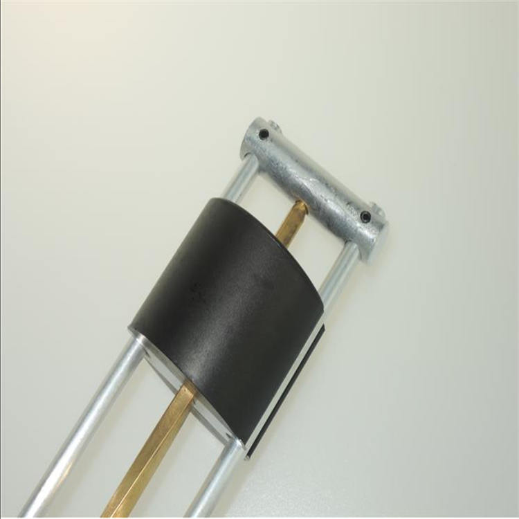 The mechanical oil gauge is divided into vibration-resistant oil pressure gauge and anti-vibration oil pressure gauge. The vibration-resistant oil pressure gauge is filled with high-viscosity mineral oil silicone in the spiral spring tube and case, which acts as a damper, reducing pointer vibration and enhancing vibration resistance. This minimizes pointer tremors. The mechanical oil gauge integrates liquid level detection and display, requiring no external devices. It can directly display liquid level output signals. Optional; it can output 9 resistance signals. The resistance range can be customized according to customer requirements. High and low level alarm functions can be added as needed.
The mechanical fuel gauge is a traditional type that uses an oil float and a pull-string within the fuel tank to sense the level of the fuel, which is then fed back to the dashboard to display the remaining fuel amount via a pointer. The mechanical fuel gauge operates without power and can be equipped with high and low-level alarm functions as per customer requirements. The mechanical fuel gauge is a simple tool for detecting hydraulic system pressure, featuring a hollow spiral spring tube, pull rod, rack, gear, pointer, and cushioning mechanism. When checking the oil pressure with the mechanical fuel gauge, it should be in a vertical position with the line of sight perpendicular to the gauge face to accurately read the pressure value.
We commit to our business with dedication, winning the future with integrity! We pursue an endless quest, keeping pace with the times to create a future! Seeking value is the starting point of our work, creating value is the driving force of our lives, and realizing value is our enduring pursuit!
How to Use Cummins Level Gauge | Online Selection
