


Mechanical oil gauge alarm switch options include high or low alarm settings. The alarm current is less than 500mA, and the alarm point can be set at the 9/10 and 1/10 positions. Application: Widely used on fuel tanks, diesel tanks, hydraulic stations, and water tanks of various generators and engines, not recommended for use on vehicles.
Primary Function of Mechanical Oil Gauge:
1. This product combines liquid level detection and display, requiring no external equipment for direct level display. Easy to install, it is widely used on fuel tanks of various generators and engines, hydraulic stations, and water tanks, but not recommended for use in vehicles.
2. Threaded connection type: M45*2 or BSP 1 1/2 NPT 1 1/2
3. Standard Flange Method: Standard 6-hole flange or welding flange.
4. Optional liquid level alarm feature.
5. This product comes in standard lengths of 120~740mm, with custom lengths available upon customer request.
6. Operating Temperature: -40°C to +80°C
7. Display Accuracy: 5%
8. Torque Tightening: 300-400 N·m
9. Length Range: 100mm - 1500mm, lengths can be customized to customer requirements; equipped with a gauge at the top, featuring a pointer to indicate liquid level.
10. Signal Output: Optional, capable of outputting 9 resistive signals, resistance range customizable according to customer requirements.
11. Alarm Switch: Optional, available in high or low alarm settings. Alarm current less than 500mA. Alarm points can be set at 9/10 and 1/10 positions.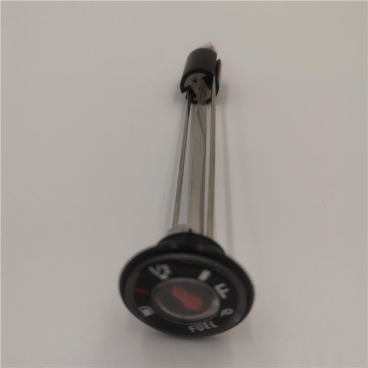 Mechanical oil gauges are categorized into vibration-resistant and vibration-proof oil pressure gauges. The vibration-resistant type features a spiral spring tube and housing filled with high-viscosity mineral silicone oil, which serves as a damping agent. This reduces pointer vibration and enhances vibration resistance. The mechanical oil gauge integrates liquid level detection and display in one unit, eliminating the need for any external devices. It can directly display liquid level output signals. Optional configurations can output 9 resistance signals, with resistance ranges customizable to meet customer requirements. High and low level alarm functions can also be added as per customer need.
The mechanical fuel gauge is a traditional type that uses an oil float inside the fuel tank and a pull cord to sense the oil level, which is then relayed to the dashboard for display through a needle. It operates without power and can be equipped with high and low level alarm functions as per customer requirements. The mechanical fuel gauge is a simple tool for checking hydraulic system pressure, featuring a hollow spring tube bent into an arc, a pull rod, a rack, gears, a needle, and a damping mechanism. When checking the oil pressure with the mechanical fuel gauge, it should be kept in a vertical position with the line of sight perpendicular to the gauge face to accurately read the pressure value.
Installation requirements for mechanical oil gauges:
Choose areas with minimal dust, no corrosive gases nearby, no severe vibration, and a considerable distance from heat sources as much as possible.
2. Flow meter installation environment temperature is -15 to 40°C.
Our entire staff is passionate and dedicated, always adhering to the philosophy of meeting customer needs, sincerity, focusing on the present, and looking forward to the future. We warmly welcome friends from all walks of life to visit, inspect, and discuss business opportunities.
Marine Level Gauge Working Principle Diagram - Online Selection
