


Model: DQ-IP2
COFDM Multi-Channel Video Transmitter User Manual
V1.0
Safety Precautions
Be sure to read the user manual before operating the DQ-IP2 transmitter.
Do not open the machine cover on your own; otherwise, the warranty will be void. Additionally, there is a risk of electric shock when touching the inside, which is extremely dangerous.
● When the DQ-IP2 transmitter is not used for an extended period, please always unplug the power cord. Additionally, do not use damaged power outlets to prevent fires and electric shocks.
Do not touch power outlets with wet hands; there is a risk of electric shock.
When disconnecting the connection wires, pull the plug, not the wire itself.
No flammable materials, metals, or liquids should be allowed to fall inside the device, as these can damage it.
To prevent damage caused by lightning, use this device under conditions with lightning rod installations. This effectively guards against losses due to lightning strikes or power grid fluctuations.
Do not install the DQ-IP2 transmitter near heat sources such as radiators or hot air ducts, nor install it in direct sunlight, dusty areas, or locations with mechanical vibrations.
The DQ-IP2 transmitter must operate in a well-ventilated environment; otherwise, it may be damaged.
Keep the original cartons and packaging materials in good condition. This way, you can easily access these materials if you need to transport the DQ-IP2 transmitter, and packaging it in the factory's original manner will provide better protection.
2 Overview

2.1 Product Features and Applications
The DQ-IP2 transmitter integrates TSoIP input, TS stream multiplexing, COFDM modulation, and power amplification. It supports IP network input for 8 SPTS (Single Program Transport Streams) and USB playback of MPTS (Multi Program Transport Streams) and SPTS files. After multiplexing, TS stream data is modulated and output as wireless signals. It is widely applicable in various fields such as drones, unmanned ships, unmanned vehicles, community data broadcasting, home entertainment, security surveillance, hotel signage, and shopping mall advertising.
2.2 Dimension and Shape
Length: 132mm
Width: 160mm
Height: 39mm
Approx. 0.5 Kg
3 Key Features
● Integrated reusability, modulation, and power amplification
Supports 8 IP inputs
Support USB drive playback of stream files
● Featuring OLED display, high contrast
● Meets EN300744 standard
● Transmission Mode (FFT) supports 2K and 8K
● Transmission bandwidth supports 6M, 7M, and 8M
Real-time monitoring of input signals supported
Supports English OLED display, front panel button operation
● High-reliability design for stable operation
4 Technical Specifications and Standards
Input | IP Interface | RJ45,10/100M |
USB Port | USB2.0,480Mbps、12Mbps | |
Transmission Protocol | Input | UDP, HTTP, supports 8 IP inputs |
Transmission Bit Rate | IP Input | 16Mbps bitrate |
USB Input | 20Mbps bitrate | |
RF Output | Bit rate: 31 Mbps | |
Output | RF Interface | SMA Interface |
Output Power | 3W | |
Frequency Range | 50MHz - 950MHz | |
Mixing Method | COFDM Standard | |
FFT | 2K、8K | |
Bandwidth | 6M、7M、8M | |
Zodiac | QPSK、16QAM、64QAM | |
Protective spacing | 1/4、1/8、1/16、1/32 | |
FEC | 1/2、2/3、3/4、5/6、7/8 | |
Universal | Dimensions | 132mm×160mm×39mm |
Weight | 500g | |
Environment | 0~45℃ (Operating); -20~80℃ (Storage) | |
Power Supply | 12V/1.5A | |
Power Consumption | 12W |
4.1 Data Interface
4.1.1 IP Data Interface
Ethernet Interface: IEEE802.3 Ethernet, RJ45 Connector
Software Agreement: Utilizes HTTP/UDP protocols
4.1.2 USB Port
Supported File Types: SPTS, MPTS Files
4.2 Radio Frequency Interface
4.2.1 Radio Frequency Output
Connector: SMA Connector
Output Frequency: 50MHz to 950MHz
Modulation Method: COFDM
Output Power: 3W
5 System Composition and Working Principle
5.1 System Composition
The DQ-IP2 transmitter schematic is as follows:

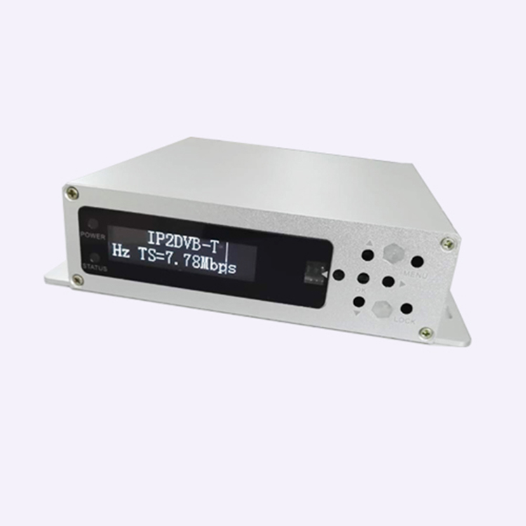
Structure Diagram (Front Panel Illustration)

1 | Power light, Status indicator light |
2 | OLED display interface |
3 | IR Remote Receiver |
4 | Up, Down, Left, Right, Confirm Button |
5 | Menu Button |
6 | Lock Button |
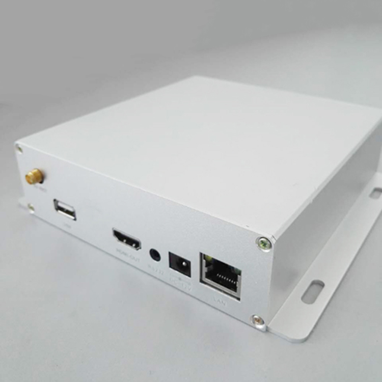
Structural illustration (rear panel illustration)

1 | RF Output Interface |
2 | USB port |
3 | HDMI Output Port |
4 | RS232 Serial Port |
5 | DC12V Power Interface |
6 | Ethernet Interface |
6 Front Panel Operation Instructions
6.1 Keyboard Functions
◀Left, ▶Right click: Move cursor and modify parameters.
▲Up, ▼Down keys: Menu page flipping and parameter modification;
OK Button: Selection to enter submenus and confirm changes to new parameters and execute functions.
Menu Key (MENU): Enter the main menu or go back to the previous menu level.
Lock Key (LOCK): Lock/Unlock panel button
Note:
A. While the keyboard is locked, press any key to activate the panel. Press the lock key to unlock the keyboard and access the main menu.
B. The keyboard will automatically lock after 60 seconds of non-operation.
6.2 Menu Selection
6.2.1 Main Interface and First-Level Submenu
The main interface is as shown below, displaying system information. RF stands for Modulation Frequency, and TS represents the Input Bit Rate.

Press the MENU key to enter the first-level submenu:
1 Output Setting: COFDM Modulation Parameters and RF Output Switch Control
2 Network Settings
3 Select the TS Input Setting to choose the source of the TS stream, from network or USB.
4 Save Config Parameters to Flash
5 Load Config from Flash to load setting parameters
6 Version shows hardware and software version information.

6.2.2 Output Settings
"Is the 'RF Enable' setting turned on for the modulator output?"

6.2.3 Network Settings
"Display the MAC Address of This Device"

6.2.4 Additional Settings

6.3 Panel Operation Procedure
Press the MENU button to enter the first-level submenu, then press the ▲▼ keys to switch between menus, press the OK button to confirm the menu, and enter the submenu.
Then press the ◀▶ button to switch settings items, press ▲▼ to adjust parameters. After setting the parameters, press OK to confirm the changes. Once the changes are complete, if you want to save the settings to the Flash, go to the "Saving Config" menu, save the parameters to Flash, and the saved settings will automatically load upon next power-up. If the parameters are not saved, the new settings will not be loaded upon next power-up.
6.4 System Boot Process
After powering on the system, the OLED panel displays BOOT, followed by ON. It then loads configuration parameters from Flash, and displays the main interface while scrolling information.
6.5 System Operation Errors and Troubleshooting
6.5.1 Indicator Status
The panel features 2 LED indicator lights, as follows:
1 "POWER" indicates the power supply, the indicator light (red) turns on when the power switch is turned on, indicating that the device's power is functioning normally.
The "STATUS" indicator light is on (green), indicating the equipment is operating normally.
6.5.2 Common Fault Exclusion
6.5.2.1 "POWER" indicator light is not illuminated
Please check if the power adapter is providing a 12V voltage output and is properly inserted into the DC socket.
6.5.2.2 "STATUS" indicator light is not illuminated
The equipment is not functioning properly; check if the network parameter settings are correct.
