


- AllProduct Category
-
Electromagnetic Flow Meters Series
Electromagnetic Water Meters Series
Open Channel Flow Meters Series
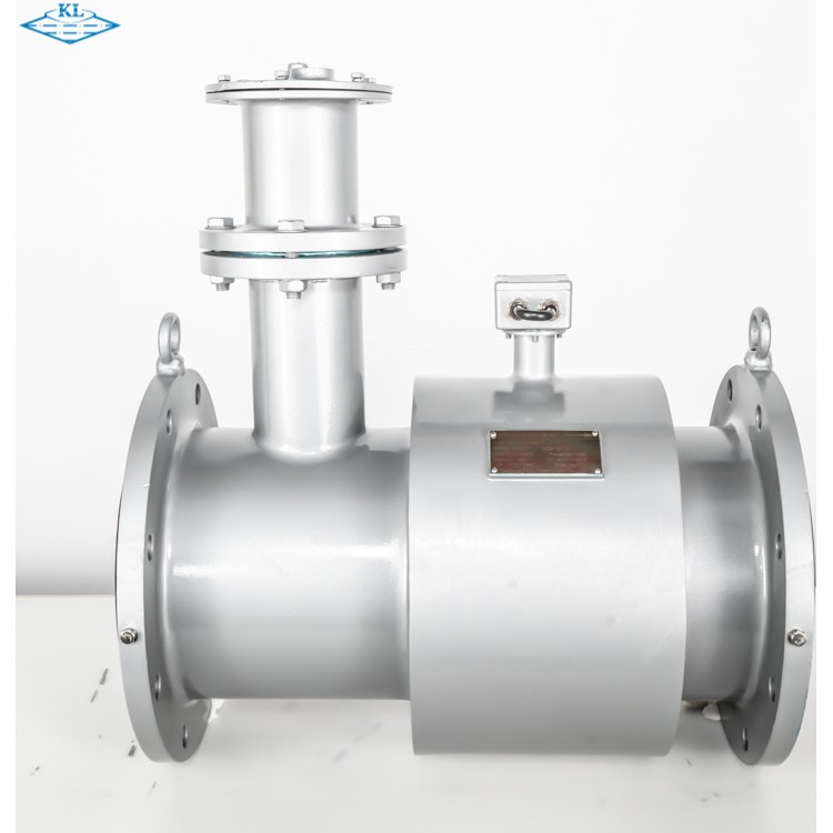
Electromagnetic Flowmeter
Ultrasonic Flow Meters
Unfull-tube Electromagnetic Flow Meter
All-Channel Wide Channel Flow Meter
Special Function Converter
Miscellaneous Accessories


详情描述
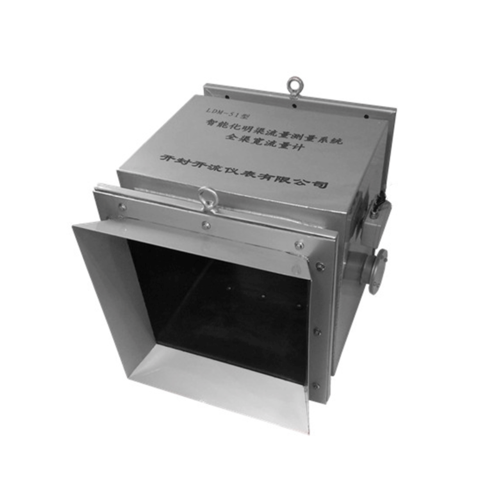
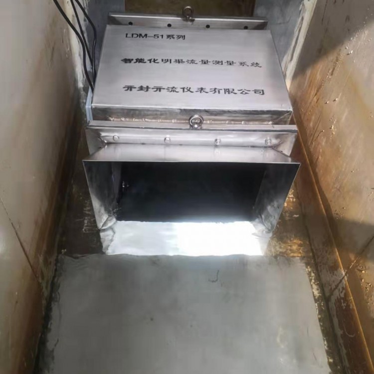
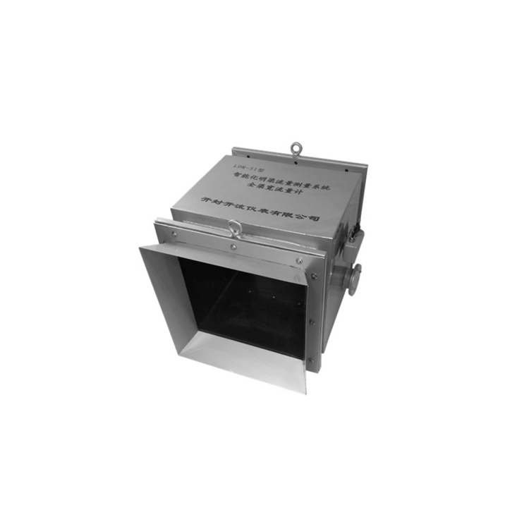
LDM-51 Intelligent Open Channel Flow Measurement System
—— Integrated闸 Control and Full Channel Flow Meters
(US Patent Product: 201930094843.6)
I. Product Introduction
LDM-51 Intelligent Open Channel Flow Measurement System - The闸控一体化全渠宽流量计 is the only intelligent open channel flow meter that can directly measure the average flow velocity across the cross-section of the channel.
Compared to other current flow measurement methods, this system directly provides area average velocity, whereas conventional ultrasonic transit time, Doppler, or other measurement principles yield line average or local average velocities. Overall, this system boasts higher measurement accuracy and is widely used for measuring conductive fluids in various fields due to its immunity to temperature, pressure, viscosity, and density. It encompasses all the advantages of an electromagnetic flowmeter. Its broad adaptability and wide measurement range play a crucial, irreplaceable role in environments with varying sediment content and significant temperature differences.
The system plays a crucial role in addressing the current challenges of metering demands. Traditional throttling devices, construction water metering, and open channel flow measurement through sluice openings suffer significant head losses, affecting downstream water usage. Acoustic metering instruments are greatly affected by environmental temperature, fluid flow state, bubble changes, and impurity content variations, making it difficult to ensure stable, reliable, and accurate measurement. Non-contact surface velocity measurement instruments, especially those measuring low flow rates, have a critical threshold that is too low to overcome the influence of wind and rain, and are still limited to flood peak warning stages. For low flow rate water measurement in branches, ditches, and small canals, all previous water measuring equipment requires on-site calibration, which is extremely difficult to obtain true values. Therefore, the traceability of measurement values is a challenging issue to resolve.
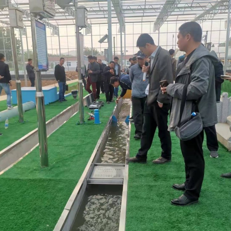
Intelligent Open Channel Flow Measurement System – Full Channel Width Flow Meters offer one-to-one factory real flow verification to ensure a perfect, precise, and reliable solution for flow measurement in different environments. The equipment is capable of measuring flow, velocity, and cross-sectional areas in both regular and irregular channels, both open and closed. It has received unanimous praise from local hydraulic departments in Ningxia, Inner Mongolia, Sichuan, Anhui, Shandong, Jiangsu, and other regions!
Section 2: Measurement Principle
Measurement Principle Diagram
The full channel wide channel flow measurement system employs the velocity-area method as the basic measurement principle.
The system operates by laying a full-width excitation system across the overcurrent cross-section to generate a vertical full-width magnetic field. The measured potential difference, which is the result of the water flow cutting through the magnetic field, represents the collective potential of all particles within the cross-section. Therefore, the measured flow velocity is the average velocity of the cross-section, i.e., the average flow velocity of the cross-section. Multiplying the average cross-sectional velocity by the area of the cross-section yields the instantaneous flow rate of the channel. The area of the cross-section is a function of the water level, which can be measured using different types of level gauges, such as ultrasonic, pressure, float ball, etc.
Section 3: Features and Functions
The system can measure water level, average flow rate, instantaneous flow rate, and cumulative flow rates in both directions.
A reasonable mathematical model combined with multi-electrode measurement technology can accurately measure the cross-sectional flow velocity in different forms.
Wide measurement range (0.01-10 m/s), bidirectional flow measurement.
Measurements are unaffected by floating debris, bubbles, sediment content, water level changes, temperature, etc.
Flow rate sensors are easy to install and do not produce resistance to water flow. They can be directly installed without modifying the standard cross-section, featuring low installation difficulty and cost.
Instrument display function: capable of simultaneously displaying water level, average velocity across the cross-section, instantaneous flow across the cross-section, cumulative flow, etc.
The matching gate can achieve precise measurement and control integration, measuring water levels before and after the gate, as well as the opening degree of the gate.
Features permanent data retention, allowing for the saving of settings and traffic values even during prolonged power outages.
The instrument features a 485 interface with standard Modbus (RTU) output and a dual-channel analog input interface for配套 use.
IV. Technical Specifications
Please provide the Chinese content to be translated.
Please exchange
Appliance
Accuracy
Water level ±2mm; flow rate ±0.5%; system ≤±2.5% (production qualification)
Measurement Range
Flow rate: 0.01-10 m/s
Power Supply
3.6/12V/24V/220V/Solar Power Supply (Optional Multiple Power Supply Methods)
Communication Methods
RS485 MODBUS (RTU) Protocol
Protection Level
IP65
Cumulative traffic displays a higher value.
9999999999
Instant flow display shows a higher value
10000
Flow Rate Display Shows Higher Value
19.999
Level Display: Higher Value
19.999
Power Consumption
<5W
Transmitted
Feel
Appliance
Flow Rate Sensor
Faraday's Law of Induction Principle (Dimensions customizable as per model specifications)
Level sensor
Pressure, Ultrasonic, Radar, Magnetostrictive (other options available)
Signal Cable
Standard 10 meters ( customizable )
Protection Level
IP68
Select
Available
Piece
Accessories selection
Solar-powered systems, mounting brackets, bracket embedment parts, stainless steel instrument boxes, battery burial boxes, communication modules
V. Model Specifications and Selection
All
Channel
Wide
Electrical
Magnet
Flow
Quantity
Please provide the Chinese content you would like translated into American English.
Water Level Range
mm
Free Traffic Range
(m³/s)
Model LDM-51-QR (Square)
Length L (mm)
Height H (mm)
Width B (mm)
Specs
1000
0.002~0.08
560
290(540)
335(295)
201
0.006~0.200
710
490(740)
535(495)
401
0.015~0.500
950
695(945)
735(695)
601
0.030~0.950
1240
930(1180)
950(930)
801
2000
0.055~1.300
1200
1130(1380)
1150(1130)
102
0.070~1.500
1670
1330(1580)
1360(1330)
1201
0.075~2.000
1980
1530(1780)
1560(1530)
1401
0.08~2.600
2180
1730(1980)
1760(1730)
1601
Note: Other specifications are available for customization (the data in parentheses represents the dimensions of the ultrasonic level gauge)
All
Channel
Wide
Electrical
Magnet
Flow
Quantity
Please provide the Chinese content to be translated.
Water Level
Range
mm
Unrestricted Traffic Range
(m³/h)
Model LDM-51-QJ (Round)
Length L (mm)
Height H (mm)
Width B (mm)
Specs
1000
0.07~15.0
280
244
160
50
0.03~60.0
420
324
240
101
1.10~250.0
560
444
360
201
4.50~1000.0
790
690
640
401
10.0~2100.0
1010
875
800
601
Other specifications are available for customization (contact and non-contact level gauges).
*Technical specifications may be subject to change without prior notice.
Selection Principle: First determine the cross-sectional shape; design for a larger flow rate multiplied by 1.2, and then find the closest match. For instance, if the designed larger flow rate is 0.8 m³/s, multiplying by 1.2 results in 0.96 m³/s. The closest match would be 1.28 m³/s, so you should choose the LDM-51-QR801.
Section 6: Installation and Maintenance
Usage Instructions:
1. Opt for a straight stretch of channel or river for installation, and select a gauge size close to the channel width.
2. All connections of the intelligent open channel flow measurement system should be kept as short as possible, avoiding power lines whenever possible. Ensure proper waterproofing, moisture-proofing, anti-breakage, and shielding treatments for the cables to guarantee accurate and error-free connections.
3. Select a flow meter with a matching diameter for gate control installation.
1. Flush-mounted installation
2. Expansion type installation
3. Circular form submersible installation
Case Study Showcase