


Overview:
intrinsically safe metal tube float flow meter(The Metal Tube Rotameter) is a commonly used variable-area flow measurement instrument in industrial automation process control. It features a small size, wide detection range, and ease of use. It is suitable for measuring the flow of liquids, gases, and steam, particularly for low flow rates and low volumes. Over the years, the metal tube float rotameter has been widely applied in industries such as petrochemicals, steel, power, metallurgy, light industry, food, pharmaceuticals, and water treatment, thanks to its excellent performance, reliability, and favorable performance-to-cost ratio.
Flowmeter Type:
TF SeriesMetal Tube Float Flow MeterConsisting of a measuring tube (sensor) and an indicator (electronic converter), different types of measuring tubes and indicators can be selected to assemble into various complete units, catering to on-site requirements.
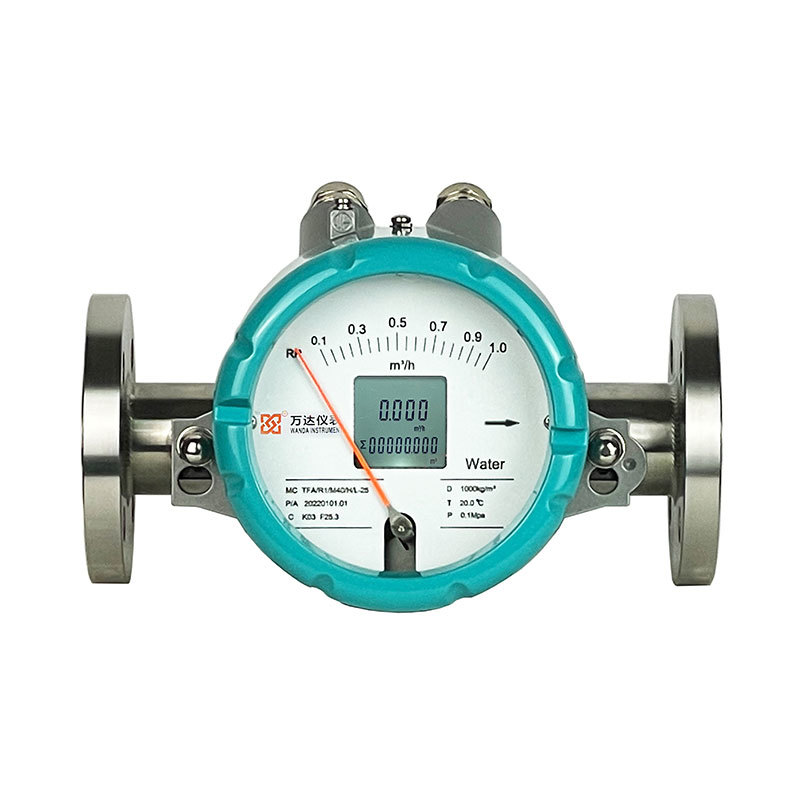
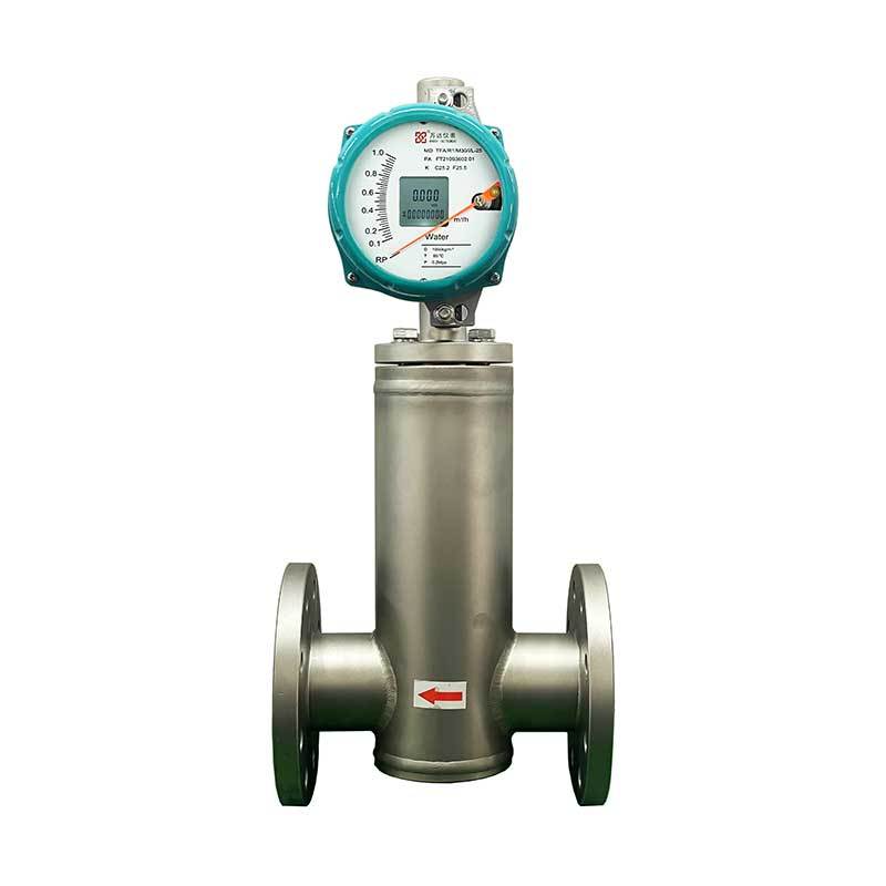
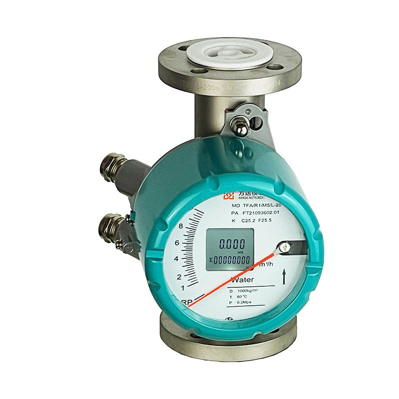
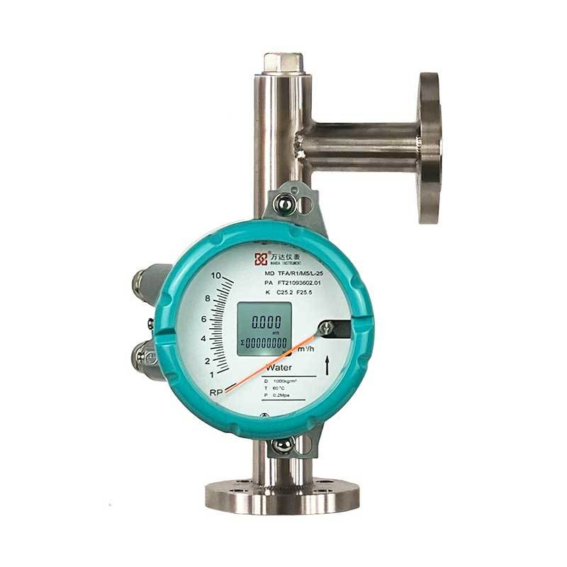
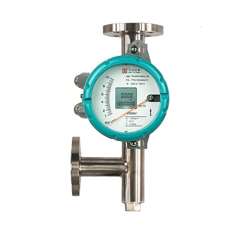
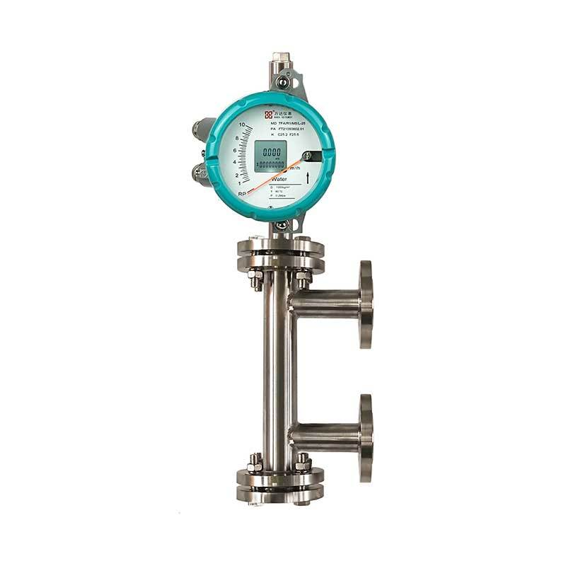
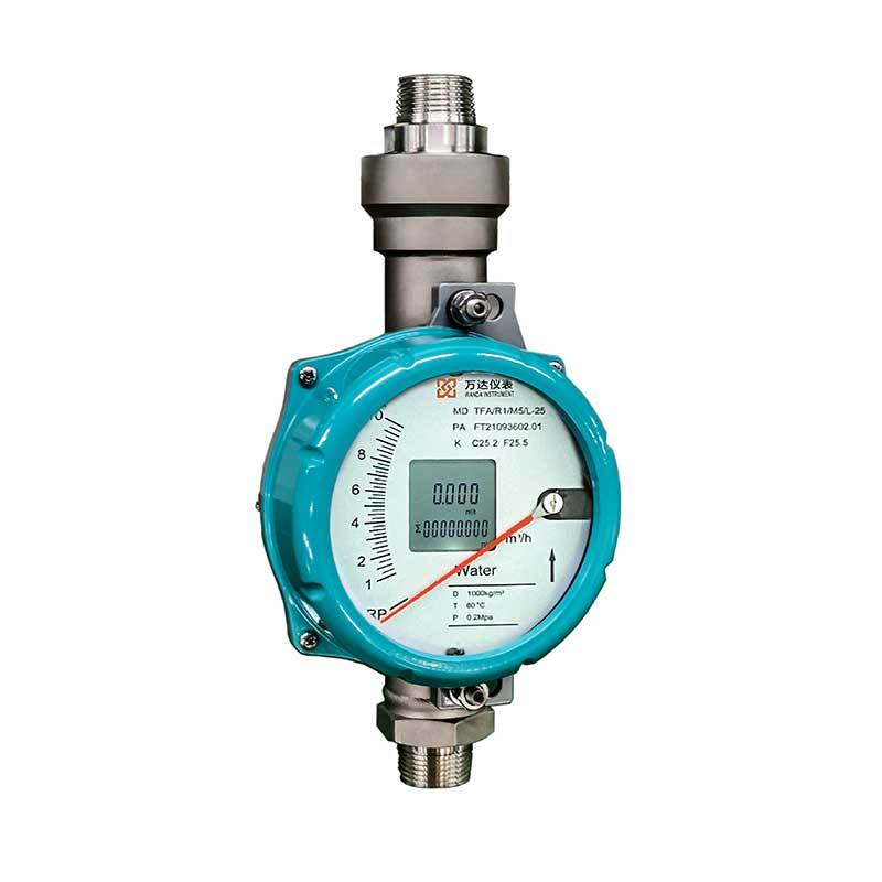
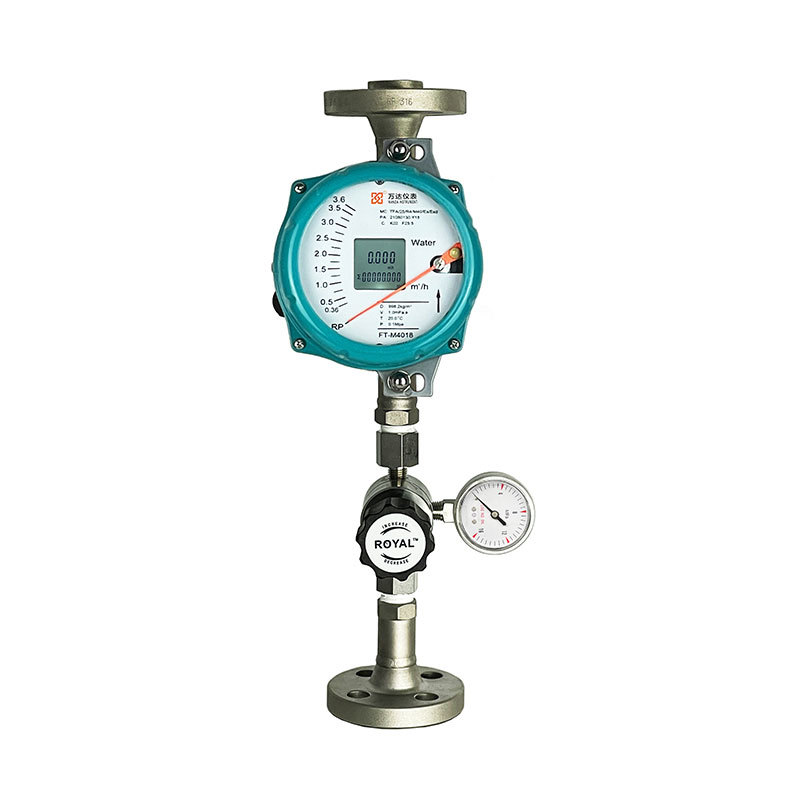
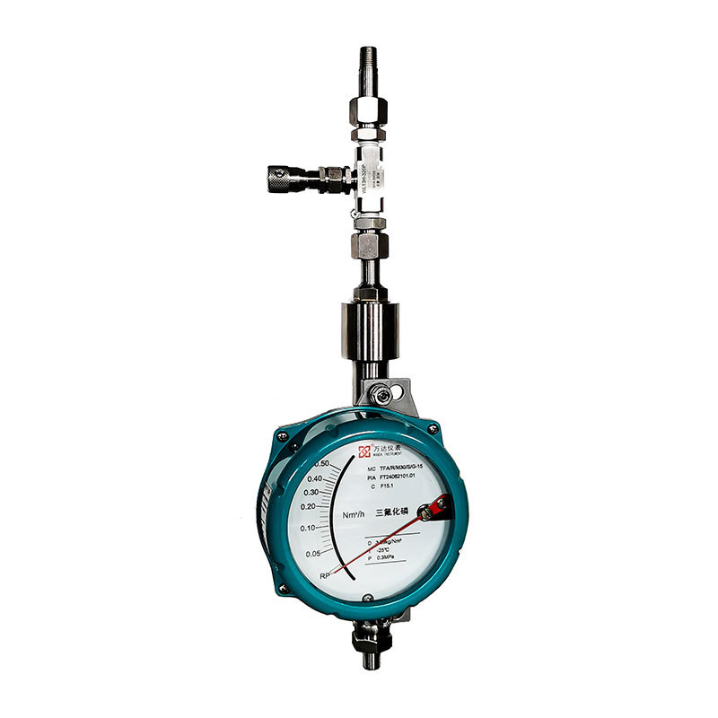
The TF series metal tube float flowmeters are categorized into 5 types based on the direction of the fluid's inlet and outlet: vertical type, horizontal type (further divided into horizontal T-type and horizontal spring type), bottom inlet and side outlet type, side inlet and side outlet type, and side inlet and top outlet type. Each type offers standard, high-temperature, jacketed, and other versions.
Level-mounted flowmeters: Use T-type structure for diameters less than or equal to DN50, and spring structure for diameters greater than DN50.
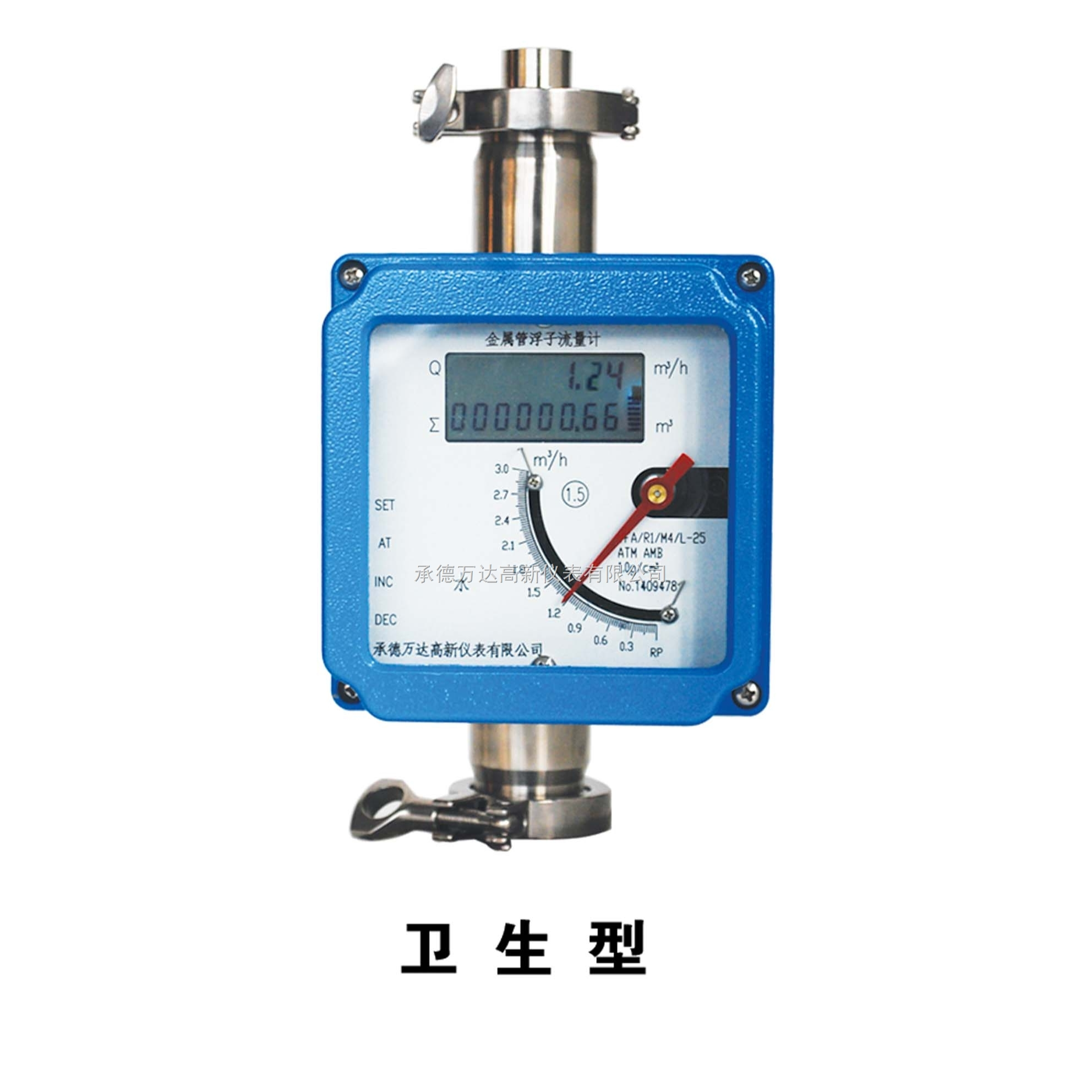
Flowmeter Connection Specifications: The TF series metal tube float flowmeter standard model adopts the GB/T9119-2000 flange standard, and the flange standard can be customized according to customer requirements. Threaded and clamp connection methods are also available.
Indicator Selection:
Users can select on-site display, electrical remote transmission, intrinsic safety, explosion-proof, or HART protocol-compatible models based on actual site requirements. Detailed functional descriptions of various indicators are listed below.
Indicator Type
Instrument Function Description
M1 Model
Local pointer indicates flow rate; no power required, no 4~20mA remote transmission; optional flow alarm device; scale dial available with either instantaneous flow value or percentage scale value.
M3 Model
Local digital display, battery-powered, without 4~20mA remote transmission, non-explosion proof. LCD shows instantaneous and cumulative flow rates, with on-site buttons for viewing and modifying related parameters. Battery lasts for 6 months, replace the battery (model ER26500, 3.6V, 7.5Ah, -55℃~85℃) when the T character appears on the display.
M4 Model
Electrical remote transmission, inherently safe design, explosion-proof mark ExdⅡCT6, optional HART protocol functionality. DC24V power supply, local pointer indicates instantaneous flow and digital display for instantaneous and cumulative flow. Two-wire system 4~20mA output, panel features 4 buttons for viewing and modifying internal parameters. For detailed instructions, refer to page 18.
M5 Model
Electrical remote transmission, explosion-proof design with ExdⅡCT6 marking, optional HART protocol function. Powered by DC24V, features on-site pointer indicating instantaneous flow rate and digital display for both instantaneous and cumulative flow rates. Two-wire system with 4~20mA output. The panel is equipped with 4 buttons for viewing and modifying internal parameters.
Feature Highlights:
◆ Ideal for low flow rate and small bore medium flow measurement ◆ Reliable operation, minimal maintenance, and long service life
◆ No strict requirement for straight pipe section ◆ Wide range ratio of 10:1
◆ Two-line LCD display, instantaneous/accumulative flow rate displayed on-site ◆ The indicator features a keypad for easy operation and settings
◆ Full metal structure, suitable for high temperature, high pressure, and strong corrosive media ◆ Non-contact magnetic coupling transmission
◆ Suitable for flammable, explosive hazardous environments ◆ Available in DC power supply or battery-powered options
◆ Data recovery, data backup, and power failure protection features ◆ Multi-parameter calibration function
Technical Specifications:
Flowmeter sizes: DN15, DN25, DN50, DN80, DN100, DN150 (other sizes available upon consultation with the manufacturer)
Flow Range: Liquid: 1.0~150,000 l/h; Gas: 0.05~3,000 m³/h (see page 11 for detailed flow rates)
Range Ratio: 10:1, 20:1 (Special)
Accuracy: 1.5 Class, 1.0 Class (Special)
◆ Pressure Class: DN15, DN25, DN50: 4.0MPa (max. 20MPa)
DN80, DN100, DN150: 1.6 MPa (max: DN80: 10 MPa; DN100: 6.4 MPa; DN150: 4.0 MPa)
Medium Temperature Standard: -30℃ to +120℃; High Temperature: 120℃ to 350℃
Power Supply: 24VDC (12-36VDC)
Output Signal: 4-20 mA DC (two-wire system), with optional HART protocol
Output Load 500Ω (when powered by 24V)
◆ Environmental Temperature: Local Type: -40℃ to 120℃; Remote Type: -30℃ to 60℃
Storage Conditions: Temperature: -40℃ to 85℃; Humidity: ≤85%
◆ Connection Method: Flanged connection, Flange Standard: GB/T9119-2000, Users may (other connection methods can be negotiated with the manufacturer)
Cable Interface M20×1.5
◆ Shell Protection IP65
Explosion-proof Mark: Intrinsically Safe Type: ExiaIICT6, Flameproof Type: ExdIICT6
Pressure Loss, see Flow Chart
◆ Medium Viscosity: DN15: η<5 mPa.s, DN25: η<250 mPa.s, DN50-150: η<300 mPa.s
◆ Liquid Receiving Material R1: 304, 1Cr18Ni9Ti; Ro: 316, 0Cr18Ni12Mo2Ti
RL: 316L, 00Cr17Ni14Mo2Ti; Ti: Titanium alloy; Rp: Polytetrafluoroethylene lining.
Magnetic Filter
If the medium contains ferromagnetic particles, a magnetic filter should be installed before the flowmeter inlet.