


Product Description
Brand Hoekou Group Model CFW-60/0.8
Material: Stainless Steel, Diameter: 2916mm
Application Range: -162℃; Volume: 60,000L
Heat Exchange Area See Drawing m² Ambient Temperature See Drawing °C
Wall Thickness: 8mm, Dimensions: φ2916*14929mm
Origin: Shandong Heze

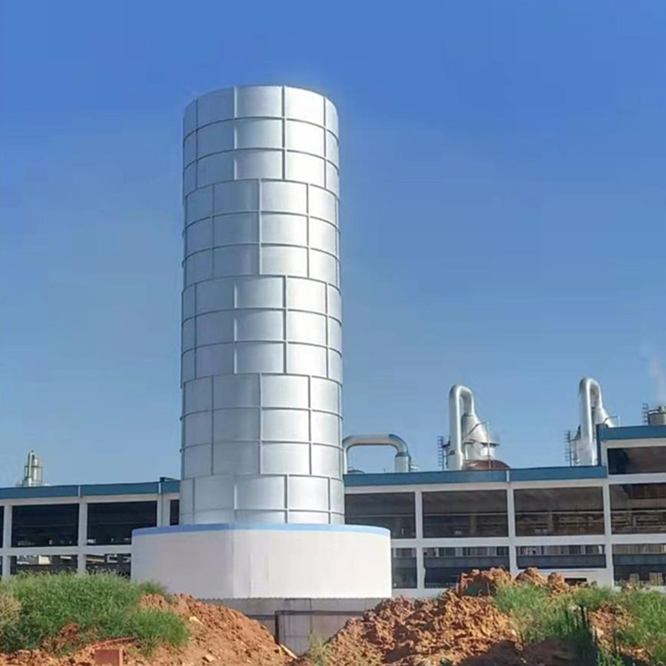
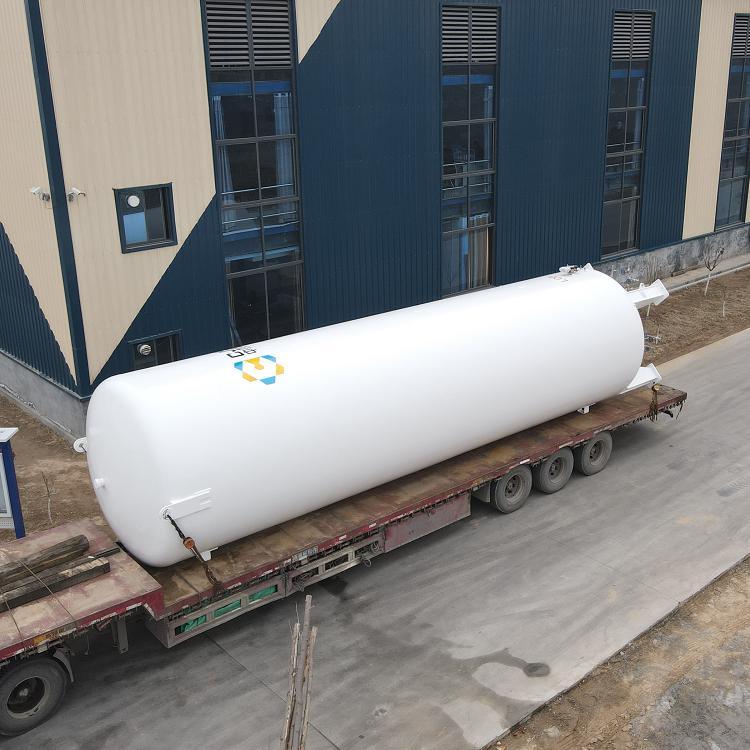
LNG Tank, Low-Temperature Natural Gas Tank, 60 Cubic Meter LNG Tank, Imported Paint from the USA, High Vacuum Level
1. Preparatory Work
Tanks should undergo airtightness tests, purge treatments, and valve and instrument inspections before being put into use.
1.1 Airtightness Test
The tank should undergo a system airtightness test after installation is complete or the inner cylinder returns to normal temperature, prior to filling with low-temperature liquids. The test pressure should be the tank's maximum working pressure, and the test gas should be oil-free dry air or dry nitrogen. The test duration is determined by the tank size but must not be less than 4 hours.
1.2 Blowing Treatment
After the airtightness test passes, the inner tank system must be purged with oil-free dry air or dry nitrogen to remove moisture. After purging with dry air or nitrogen, the product gas should also be used for purging. During purging, gases lighter than air are added from the top via the vent valve, and the bottom is drained through the liquid inlet and outlet valves. To accelerate the removal of moisture inside the tank, the purge gas can be heated to 80-100°C. Each pipe and valve should be purged individually, especially the level gauge and pressure gauge, which should be purged from the joints to remove moisture from the pipes. This should continue until the dew point of the gas exiting the inner tank system meets the requirements before filling can begin.
1.3 Valve Instrument Inspection
Before filling with low-temperature liquid, it is essential to check that the valves are in the correct position, that the instruments are responsive and reliable, and that the liquid level gauge's inlets are unobstructed.
2. Filling: Initial filling and top-up filling.
2.1 Initial Filling (referring to the filling when the inner cylinder is in a heated state). The steps are as follows:
2.1.1 Connect the filling pipeline.
2.1.2 Perform blowout on the filling pipeline (this should be done before each filling), and before the upper liquid inlet and outlet valves are opened, place a small amount of liquid into the output pipeline from the liquid source valve. Simultaneously, open the pipeline residual liquid drain valve and clean the pipeline to remove moisture and dust impurities.
2.1.3 Open the inner tube vent valve and pressure gauge valve, and simultaneously start the level gauge.
2.1.4 Open the upper liquid inlet valve, allowing liquid to enter from above. Since the inner cylinder is in a hot state, the opening of the upper liquid inlet valve should be small to gradually cool the pipeline and inner cylinder to the temperature of the liquid being filled. Once the inner cylinder's vent valve stabilizes the exhaust, you can open the upper liquid inlet valve wider to increase the filling speed.
2.1.5 Upon the liquid level gauge indicating a liquid level, open the liquid inlet and outlet valves, and close the upper liquid inlet valve to switch from upper to lower liquid inlet.
2.1.6 When the liquid fills the indicator valve (already opened) and sprays out, it indicates that the storage tank is full of liquid. Immediately close the liquid inlet and outlet valves, stop filling, and open the pipeline residual liquid discharge valve to expel the remaining liquid-gas mixture in the filling pipeline.
2.1.7 Disassemble the filling pipeline after the filling process is complete.
2.2 Additional Liquid Charging (referring to the inner cylinder already having low-temperature liquid, no longer requiring cooling of the inner cylinder)
2.2.1 Similar to the initial filling, the difference is that the filling quantity can be increased from the start, and close attention must be paid to pressure changes during the filling process. If liquid is directly introduced through the liquid inlets and outlets, when the pressure rises significantly, to reduce the pressure, switch from bottom (lower) filling to top (upper) filling.
2.2.2 Additionally, from the perspective of pressure, it can be categorized into atmospheric filling and pressurized filling.
2.2.3 During the atmospheric filling process, the inner cylinder vent valve is always open, allowing the inner cylinder to be in communication with the atmosphere, hence the name "atmospheric filling."
While under pressure filling, the vent valve is closed, and the pressure inside the tank is higher than atmospheric pressure, hence the name "pressurized filling." However, the working pressure of its storage tank should be greater than 2 Kg/cm². Whether under standard atmospheric pressure or engineering atmospheric pressure, 1 Kg/cm² = 98100 Pa = 0.0981 MPa.
3. Boost Pressure
When transferring the liquid in the tank to another storage tank or for vaporization, the internal cylinder pressure needs to be increased. The increase in pressure should be determined based on the actual usage requirements of the user, but it must not exceed the maximum working pressure of the storage tank.
The boost program is:
3.1 Check if the pressure gauge and level gauge are in working condition.
3.2 Ensure the gas valve is fully open.
3.3 Open the turbocharger inlet valve (boost valve) slowly to allow the liquid to vaporize in the turbocharger. If the draining speed is fast, the inner cylinder pressure will drop quickly, and you can open the boost valve wider. When the pressure reaches the required working pressure, reduce or completely close the turbocharger inlet valve. At this point, the liquid inside the turbocharger will continue to evaporate to the required pressure. During the boost process, closely monitor the pressure gauge readings.
4. Liquid Discharge
Three forms of liquid discharge
4.1 Carburetor Drain
Once the pressure inside the tank reaches the required level, the drain valve can be opened to supply liquid to the vaporizer, heating it to vaporize and send it to the usage site. This is the primary drainage method for tanks equipped with a vaporizer.
4.2 Liquid draining through进出口 valves
This draining process involves supplying liquid to tanker trucks or larger storage tanks using输液软管 (infusion hoses), and its operational procedure is essentially the same as for filling, with the only difference being that the liquid inlet and outlet valves switch from intake to discharge.
4.3 Discharge through a drain valve (also known as a liquid drain valve) or directly through a Dewar tube
This drainage method supplies liquid to portable small containers like Dewar flasks by connecting the metal flexible hose of the small container to the drainage valve (or through a Dewar tube), then opening the liquid outlet valve to provide the liquid. This type of drainage has a lower volume and may not require pressurization for fixed storage tanks depending on the specific circumstances, allowing for liquid supply without it.
5. Storage
Liquid storage includes two methods: atmospheric storage and pressurized storage.
5.1 Atmospheric Storage
During atmospheric storage, the vent valve on the inner cylinder remains open to allow gases from natural evaporation to escape into the atmosphere, preventing the tank pressure from rising. Since the natural evaporation is minimal, the vent valve only needs to be slightly open. (The opening should be adjusted to maintain constant tank pressure.)
5.2 Pressure-Vessel Storage
During the pressurized storage process, the vent valve is closed. As the gaseous substance from natural evaporation remains inside the tank, the internal cylinder pressure gradually increases. At this point, the pressure gauge shows pressure. When the internal cylinder pressure reaches the working pressure, the vent valve should be immediately opened to relieve pressure.
6. Issues with simultaneous filling and draining fluids
Many situations require a continuous supply of gas, which can be met if there are two or more tanks. However, for a single storage tank, whether the gas supply can be continuous hinges on whether simultaneous charging and discharging can be achieved. Generally, when refilling liquid into a fixed storage tank using tank trucks, simultaneous charging and discharging should meet the following conditions:
6.1 The working pressure of fixed storage tanks should be above 0.02 Mpa.
6.2 During the liquid filling process, the upper liquid inlet valve and the liquid inlet and outlet valves should be frequently adjusted, as filling from the top (upper section) can reduce the tank's pressure, while filling from the bottom (lower section) can increase the tank's pressure.
6.3 When filling and draining simultaneously, if the liquid is entering from the bottom and still cannot meet the pressure requirements, you can open and adjust the size of the pressure booster valve to maintain stable pressure within the tank.
7. Maintain
7.1 Do not tamper with the outer cylinder explosion-proof device and vacuum valve; otherwise, it will destroy the vacuum degree of the storage tank.
7.2 The shell is an external pressure vessel that withstands atmospheric pressure. It is strictly prohibited to collide with it to prevent damage to the shell, which may affect the vacuum degree.
The tank vacuum level should be checked every six months. To measure, simply unscrew the protective cap on the metal thermowell and insert the plug of the thermocouple vacuum gauge, and you can determine the true vacuum level of the jacket.
7.3 After several years of use, the vacuum level in the storage tank may drop below 66.66 Pa, at which point a re-vacuuming is required.

LNG Tank, Low Temperature Natural Gas Tank, 60 Cubic Meter LNG Tank, Imported Paint from the USA, High Vacuum Degree
Product Description
Brand Hegu Group Model CFW-100/0.8
Material: Stainless Steel, Diameter: 3400mm
Application Range -162℃ Volume 100,000L
Heat Exchange Area - See drawing m², Ambient Temperature - See drawing °C
Wall Thickness: 10/12mm, Outer Dimensions: 3424*16442mm
Origin: Shandong Heze
60-cubic-meter LNG tank price, Manufacturer supplies 30-cubic and 60-cubic LNG tanks
3. LNG Tank Fault Inspection and Handling 3.1. Daily Inspections
3.1.1 Level gauge and pressure gauge operation check.
3.1.2 Check if the shut-off valves, regulating valves, and safety valves are in normal working condition.
3.1.3 Tank, pipelines, and valves for any leaks.
3.2 Regular Inspections
3.2.1 The pressure gauge should be calibrated annually and accompanied by a certificate of inspection with a lead seal.
3.2.2 The safety valve should be calibrated annually and sealed with lead.
3.2.3 Low-temperature liquids should be analyzed every three to six months as needed for operation.
3.3 Troubleshooting
Fault occurred
Original Cause
Mitigation Measures
1. Abnormal inner tube pressure
(raise or lower)
A pressure gauge distortion
B Tank Vacuum Reduced
Valve operation error
A Pressure Gauge
B-weight vacuum extraction
C conforms to the manual's operational requirements
2 Level Gauge Distortion
Improper operation of the A level gauge valve
The B level gauge is damaged.
Reoperate as per requirements
B Replace with New Level Gauge
3 External frosting on storage tank
Vacuum Failure
B-laminate leakage
C Pearl-like Sand Sinking
A re-evacuate the vacuum
B pressure test and leak detection, then evacuate air
C balance interlayer re-install pearlescent sand and then vacuum again
Note:
1. If the user needs to vacuum or re-fill with pearlescent sand in the sandwich layer, they must first empty the inner tube of liquid and wait until it returns to room temperature before proceeding.
2. Should users encounter issues that are difficult to handle, they may contact our after-sales service department promptly. We offer a three-package quality guarantee for our products. Additionally, we also provide repair services for products beyond the warranty period and for non-our company products.
4. Cautionary Notes
4.1 The vacuum valve is sealed before the product is shipped out. Upon delivery to the user's site, the user must ensure that all pipeline valves are protected during installation, particularly the vacuum valve, and strictly prohibit collision or opening the vacuum valve.
4.2 Do not empty the liquid in the tank unless it will be unused for a long period, to prevent the inner cylinder from overheating and requiring re-cooling when refilling, which could result in unnecessary losses.
4.3 Low-temperature liquid storage tanks are used for storing liquid nitrogen, liquid oxygen, and liquid argon. However, when switching to another liquid, the original liquid must be completely emptied and purged before refilling with the new liquid.
Note:
1. The measuring full valve opens when the liquid is nearly full, closes when liquid starts to flow, and stops the inflow. For the first inflow, it should be filled from the top first, then from the bottom.
2. Open during waste liquid disposal.
3. Release the venting valve when the container pressure is too high.
4. The container automatically opens when over-pressurized. Normally, only one is in use. In case of a malfunction in the working one, the other is immediately activated to ensure the safe operation of the storage tank. The damaged safety valve is then repaired and calibrated, and upon passing inspection, it is promptly reinstalled.
5. The inner cylinder automatically starts upon opening the boost valve when pressure boosting is required.
6. The level gauge is usually turned off during normal operation.
7. Burst upon overpressure; must be replaced immediately if a burst occurs.

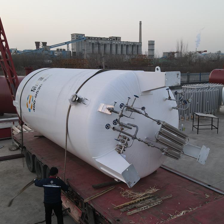
Natural Gas Storage Tank Pricing - Direct from Manufacturer for 100 Cubic Horizontal LNG Tanks, Price Discounts, High Vacuum Level


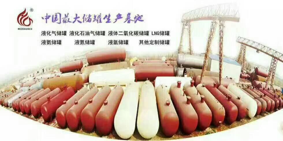
销售液化天然气储罐电话-【液化天然气储罐价格】液化天然气储罐图片-专业的液化天然气储罐哪家质量好-专业生产液化天然气储罐供应商