


Liquefied Natural Gas (LNG) Storage Vessel Capacity and Applicable Scenarios
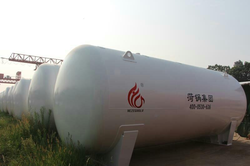
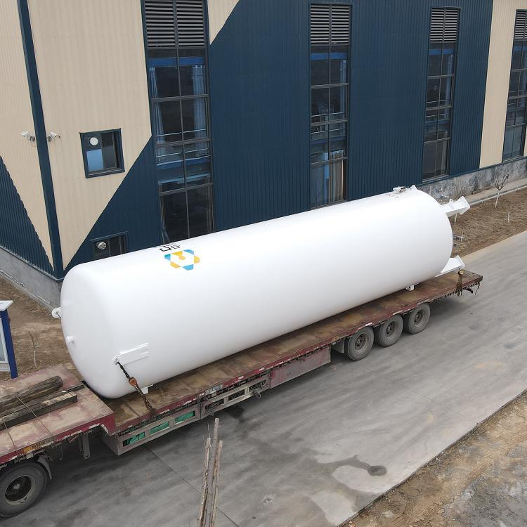
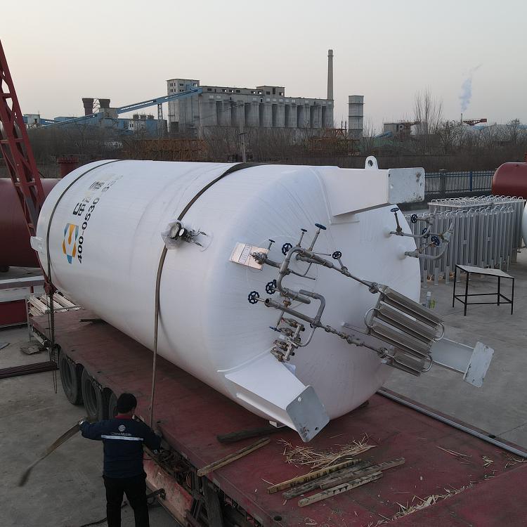
1. 60-cubic-meter LNG vacuum powder-insulated tank, available in sizes from 5 to 200 cubic meters. Suitable for residential gasification stations, industrial gasification stations, LNG refueling stations, small skid-mounted liquefaction units, and refrigerant storage.
2. Horizontal submersible low-temperature storage tanks from 300 to 5,000 cubic meters, suitable for small liquefaction units, air separation plants, civil gasification stations, industrial gasification stations, and LNG gasification stations, etc.
3. Horizontal and Lying Low-Temperature Storage Tanks, 100~10,000 cubic meters, suitable for small and medium-sized liquefaction plants, peak-shaving liquefaction plants, air separation units, LNG storage and distribution stations, LNG gasification stations, etc.
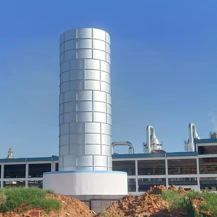
4. Vertical flat-bottomed cylindrical storage tanks, ranging from 200 to 200,000 cubic meters, suitable for various liquefaction units, LNG storage and distribution stations, LNG regasification stations, air separation units, liquid hydrocarbon storage, and coastal LNG receiving stations.
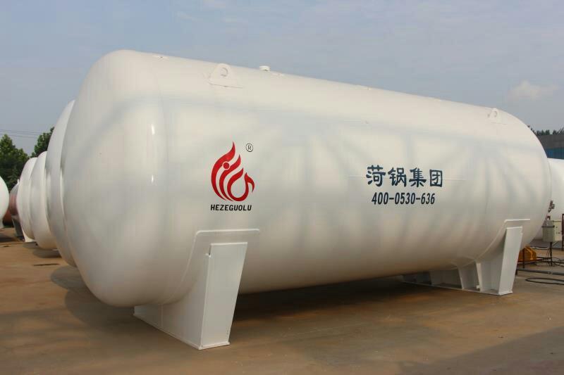
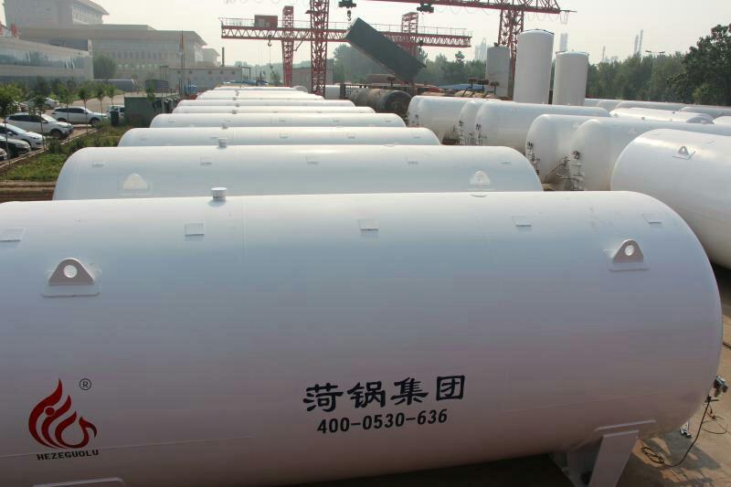
Vacuum powder insulation storage tanks are composed of an inner cylinder and an outer cylinder, with the annular space insulated using vacuum powder insulation technology. Due to transportation constraints, the maximum tank capacity is currently 200m³, and they are commonly used for storing smaller liquid volumes.
When the liquid storage capacity exceeds 200m3, a 60-cubic L NG storage tank can be connected in parallel to form a cluster tank using multiple vacuum powder insulation storage tanks. When the storage capacity exceeds 1500m3, it is advisable to use a horizontal sub-parent type low-temperature storage tank (abbreviated as sub-parent tank), which has the advantages of fewer site equipment, lower investment, convenient operation and maintenance, and safety reliability compared to cluster tanks. The sub-parent tank is composed of multiple (over 3) sub-tanks in parallel, assembled into an outer large tank (parent tank). The sub-parent tank is also limited by transportation and lifting conditions, with a maximum single tank capacity of 250m3 and a total maximum capacity of 5000m3. When the storage capacity exceeds 200m3, spherical horizontal low-temperature storage tanks and vertical flat-bottomed cylindrical horizontal low-temperature storage tanks can also be chosen. When the storage capacity exceeds 10,000m3, vertical flat-bottomed cylindrical horizontal low-temperature storage tanks are more commonly used. During the actual selection process, when the storage capacity is less than or equal to 200m3, a vacuum powder insulation storage tank with mature manufacturing and installation technology is chosen for the 60-cubic L NG storage tank.
30, 60, 100 cubic LNG storage tanks LNG gasification plant process flow
As shown in the figure, LNG is transported to the LNG satellite station by low-temperature tanker trucks. It is pressurized in the tanker trucks' storage tanks using horizontal dedicated unloading boosters set at the unloading platform. The LNG is then sent to the satellite station's low-temperature LNG storage tanks by utilizing the pressure difference. Under operating conditions, the storage tank booster increases the pressure of the LNG in the tank to 0.6 MPa. The pressurized low-temperature LNG enters an air-cooled gasifier, where it exchanges heat with air and converts into gaseous natural gas while increasing in temperature. The exit temperature is 10°C lower than the ambient temperature, with a pressure of 0.45-0.60 MPa. If the temperature of the natural gas at the outlet of the air-cooled gasifier does not reach above 5°C, it is heated by a water bath heater. Finally, after pressure regulation (with the regulator's outlet pressure at 0.35 MPa), metering, and odorization, it enters the city's transmission and distribution network, supplying various users.
1. Unloading Process
LNG is transported to the gasification station in the consuming city from the LNG liquefaction plant via highway tank trucks or tank container trucks. The empty-temperature type pressure booster gasifier on the tank truck is used to increase the pressure of the tank (or the tank container truck is pressurized using a booster gasifier set up within the station), creating a pressure difference between the tank truck and the LNG storage tank. This pressure difference is then utilized to unload the LNG from the tank truck into the storage tank at the gasification station. Upon completion of the unloading, the gaseous natural gas is recovered from the tank truck through the vapor phase pipeline at the unloading platform.
During unloading, to prevent an increase in pressure inside the LNG storage tank from affecting the unloading speed, the upward feeding method is used when the LNG temperature in the tanker is lower than that in the storage tank. The low-temperature LNG in the tanker is sprayed into the tank through the upward feeding pipe nozzle in a spray state, cooling some of the gas to liquid and reducing the tank pressure, allowing for smooth unloading. If the LNG temperature in the tanker is higher than that in the storage tank, the downward feeding method is employed. The high-temperature LNG enters the tank through the downward feeding port, mixing with the low-temperature LNG inside to cool down, preventing the high-temperature LNG from evaporating through the upward feeding port, which could increase the tank pressure and complicate unloading. In actual operations, due to the distant LNG gas sources from the cities consuming the gas, the LNG temperature in the tankers upon arrival in the consuming cities is typically higher than the temperature in the LNG storage tanks at the gasification stations, necessitating the downward feeding method. Therefore, except for the initial LNG loading, the downward feeding method is predominantly used during regular tanker unloading.
To prevent significant temperature difference stress from damaging the pipeline or affecting unloading speed during unloading, the unloading pipeline should be pre-cooled with LNG from the storage tank prior to each unloading. At the same time, rapid opening or closing of valves should be avoided to prevent sudden changes in LNG flow rate, which may cause liquid impact and damage the pipeline.
2. Storage Tank Pressure Boosting Technology
Driven by pressure, LNG flows from the storage tank to the regasifier, where it is converted into gaseous natural gas for customer use. As LNG exits the tank, the internal pressure decreases continuously, slowing down the outflow rate until it stops. Therefore, during normal gas supply operations, it is necessary to continuously replenish the tank with gas to maintain the pressure within a certain range, ensuring the continuous gasification process. The tank's pressure increase is achieved using an automatic pressure boost valve and an auto-pressurized atmospheric temperature regasifier. When the tank's pressure falls below the set opening value of the automatic pressure boost valve, the valve opens, and the LNG inside the tank flows into the auto-pressurized atmospheric temperature regasifier due to the liquid level difference (the installation height of the auto-pressurized atmospheric temperature regasifier should be below the lowest liquid level in the tank). In the auto-pressurized atmospheric temperature regasifier, the LNG is vaporized into gaseous natural gas through heat exchange with air, which then flows back into the tank, raising the internal pressure to the required operating level.
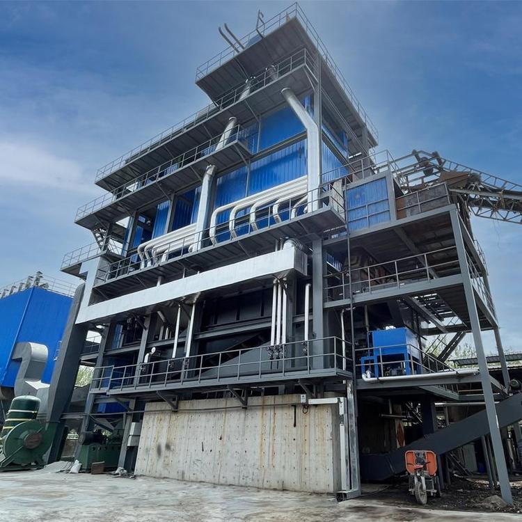
3. LNG Gasification Technology
LNG undergoes heat exchange with the atmosphere in a vacuum gasifier, transitioning from liquid to gas. At the outlet, it is 10°C cooler than ambient temperature. If it drops below 5°C, it is heated by a water bath vaporizer. The hot water for the water bath vaporizer is sourced from the water circulation of a hot water boiler.
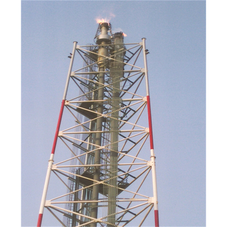
4. Safe Release Process for Gases
LNG is a liquid mixture primarily composed of methane, with a boiling point of -161.5°C at atmospheric pressure and a storage temperature of -162.3°C, with a density of approximately 430 kg/m³. When LNG vaporizes into gaseous natural gas, its critical buoyancy temperature is -107°C. If the temperature of the gaseous natural gas exceeds -107°C, it becomes lighter than air and will rise and drift away from the leak source. If the temperature of the gaseous natural gas falls below -107°C, it becomes heavier than air, and the低温 gaseous natural gas will accumulate downward, forming an explosive mixture with air. To prevent the accumulation of low-temperature gaseous natural gas from the safety valve discharge that could form an explosive mixture, a 1-unit air temperature safety vent gas heater is installed. The vent gas is first heated by this heater to reduce its density below that of air before being released into the atmosphere.
For LNG gasification stations in the south without EAG heating equipment, to prevent cold burns to the operators from the release of low-temperature LNG gas-liquid mixture after the safety valve trips, the individual safety valve vent pipes and the storage tank vent pipes should be connected to the central vent main pipe for venting.