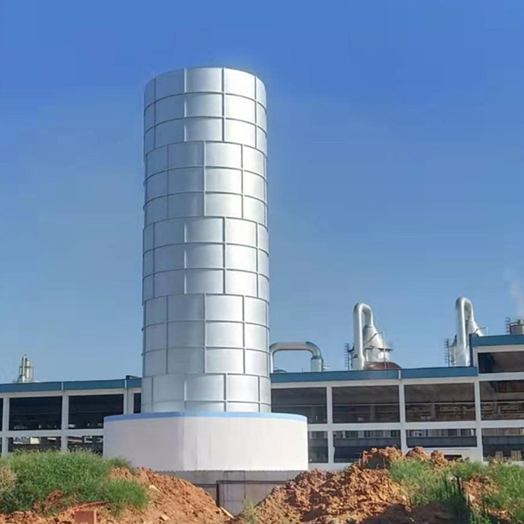


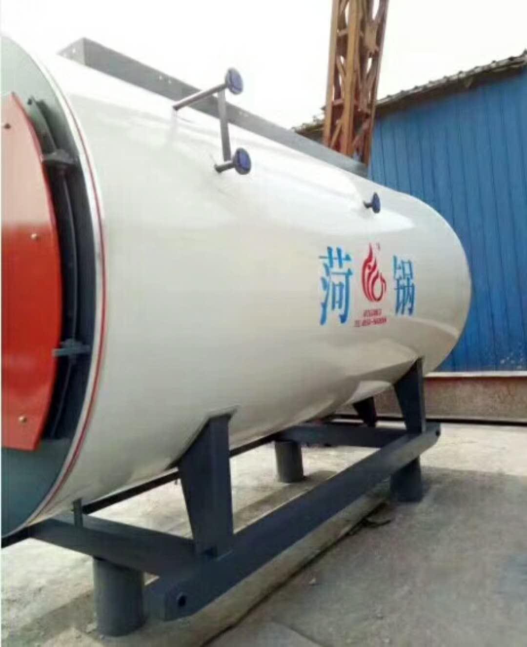


LNG Storage Vessel
LNG stands for Liquefied Natural Gas. Its primary component is methane. LNG is colorless, odorless, non-toxic, and non-corrosive. Its volume is approximately 1/600th of an equivalent volume of gaseous natural gas, and its weight is about 45% of the same volume of water. Its calorific value is around 52 MMBtu per ton (1 MMBtu = 2.52×10^8 calories).
Model:
CFL-5/0.8,CFL-10/0.8,CFL-15/0.8,CFL-20/0.8,CFL-30/0.8,CFL-50/0.8,CFL-60/0.8,CFL-100/0.8,CFL-150/0.8...
CFW-5/0.8,CFW-10/0.8,CFW-15/0.8,CFW-20/0.8,CFW-30/0.8,CFW-50/0.8,CFW-60/0.8,CFW-100/0.8,CFW-120/0.8,CFW-150/0.8…

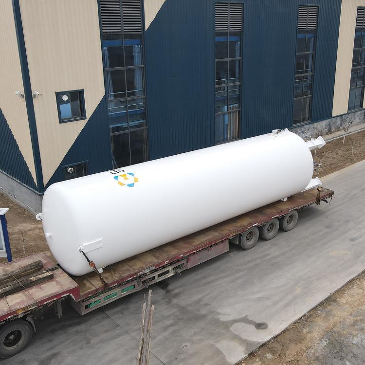
Low-temperature storage tanks are designed and manufactured in strict accordance with national standards, widely used for storing and using deep cold liquids such as liquid oxygen, liquid nitrogen, liquid argon, liquid carbon dioxide, liquid natural gas, and liquid ethylene, featuring various working pressures and specifications. Equipped with unique high-vacuum insulation technology, they offer excellent insulation properties, long-term vacuum maintenance, and extremely low operating costs. Modular piping systems and high-configured components enhance the equipment's performance, durability, and reduce maintenance costs, thereby significantly boosting your competitive edge.
Introduction:
Low-temperature thermal insulation storage tanks are vacuum powder insulation types, featuring a double-container structure composed of an inner container and an outer container, which are available in vertical and horizontal versions. The inner container, selected based on the medium to be stored, is made of austenitic stainless steel, specifically S30408. The material for the outer container varies depending on the user's location, typically Q345R. The interlayer between the inner and outer containers is filled with thermal insulation material, Pearlite sand, and then evacuated.
Usage:
Store Liquid Oxygen (LO2), Liquid Nitrogen (LN2), Liquid Argon (LAr), Liquefied Natural Gas (LNG), Liquid Carbon Dioxide (LCO2)
Insulation Performance:
Insulation materials use pearl sand filling in the sandwich layer under thermal conditions, followed by vacuum extraction. The standard vacuum degree after the sandwich layer is sealed is:
Sealing Vacuum Gauge
Design Parameters:
Design Pressure: 0.84 Mpa, 1.32 Mpa, 1.68 Mpa
Working Pressure: 0.8 MPa, 1.2 MPa, 1.6 MPa
Design Temperature: -196℃
Operating Temperature: -196℃
Effective Volume: 2.5m³, 3.5m³, 5m³, 10m³, 15m³, 20m³, 30m³, 50m³, 60m³, 100m³
Definition:
LNG stands for Liquefied Natural Gas.
The main component is methane. LNG is colorless, odorless, non-toxic, and non-corrosive, with a volume approximately 1/600th that of an equivalent volume of gaseous natural gas. The weight of LNG is roughly 45% of the same volume of water, and its calorific value is about 52 MMBtu/ton (1 MMBtu = 2.52×10^8 calories).
Formation:
The natural gas produced from the gas field is first purified and then liquefied under ultra-low temperature (-162℃) and atmospheric pressure to form liquefied natural gas.
The critical temperature of LNG between gas and liquid phases at atmospheric pressure is -162℃.
The standard commonly used in LNG production is API 620 of the American Petroleum Institute.
Meaning:
Liquefied Natural Gas (LNG) storage tanks are specialized products designed for storing LNG, and are categorized as special equipment.TwoPressure vessel category, 06Ni9DR material, completed with flaw detection, hydrostatic and pneumatic testing, on-site inspection by the Technical Supervision Bureau, issued with pressure vessel inspection certificate, and external rust removal and painting processes. The liquefied gas storage tank undergoes strict quality assessment for the material, appearance dimensions, weld quality, operational quality, installation quality, internal equipment, and safety accessories.
Routine physical and chemical tests for the cylinder material, such as mechanical properties and chemical composition.
The welding joints, welds, tank end caps, and the geometric positions of all pressure elements are rigorously inspected via X-ray non-destructive testing and magnetic particle inspection. Tests are conducted on the product's sealing, pressure resistance, and all technical indicators that could affect the safe operation of the product.
1. LNG Storage Tank System: The LNG storage system consists of low-temperature storage tanks, auxiliary pipelines, and control instruments.
2. By capacity classification:
Small natural gas storage tanks, 5-50 cubic meters, commonly used in residential gas liquefaction stations, LNG vehicle refueling stations, etc.
Medium-sized natural gas storage tanks, 50-100 cubic meters, commonly used in satellite liquefaction units, industrial gas vaporization stations, etc.
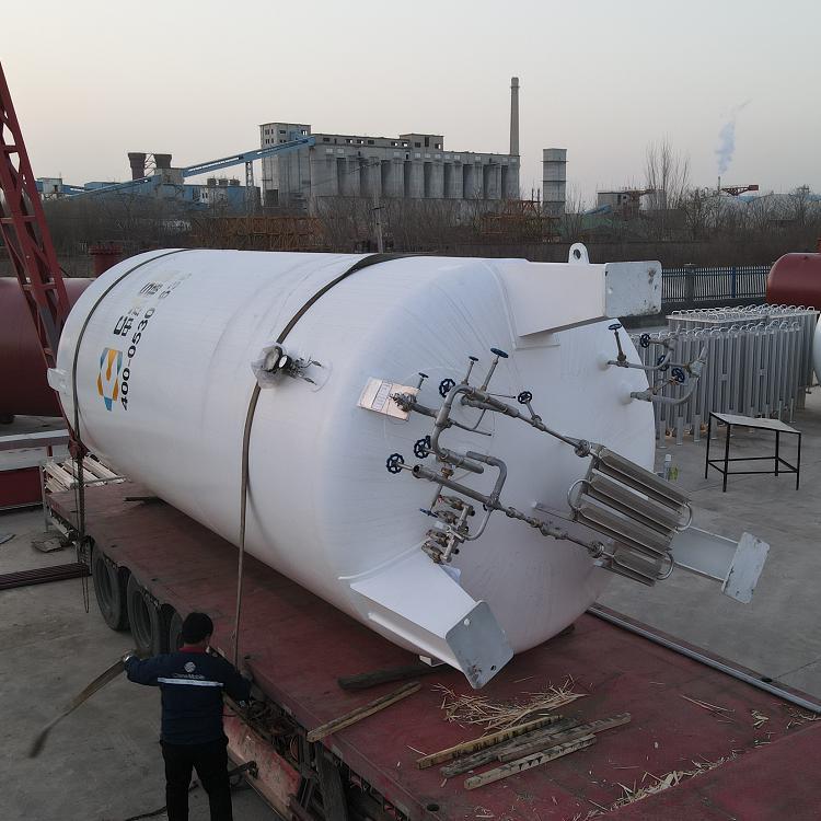
3. Natural gas storage tanks, typically use austenitic stainless steel pipes for LNG pipelines. Austenitic stainless steel pipes offer excellent low-temperature properties.
4. Vertical natural gas storage tanks (LNG tanks) featuring vacuum powder insulation technology. The inner cylinder and pipeline materials are made of OCr18Ni austenitic stainless steel, while the outer cylinder is made from high-quality carbon steel Q345R pressure vessel steel plate. Our company offers a variety of specifications ranging from 50 to 100 cubic meters of liquefied natural gas storage tanks.
5. Uses of Natural Gas Storage Tanks: Chemical fuel, residential fuel, automotive fuel, co-generation, heat pumps, fuel cells, etc.
6. Natural Gas Storage Tank Liquefaction Process: Cascade Liquefaction Process, Mixed Refrigerant Liquefaction Process, Liquefaction Process with Expander.
7. The natural gas liquefaction facility consists of a natural gas pretreatment process, liquefaction process, storage system, control system, and fire protection system, etc.

Low-temperature valve troubleshooting
Common Faults of Low Temperature Valves: Gear wheel stuffing box leakage; valve cover nut leakage; internal leakage in the valve; leakage at the valve-pipe connection.
Leakage at the handwheel stuffing box or valve cover nut can be tightened with a wrench when the storage tank is not pressurized; it is strictly prohibited to tighten under pressure.
Valve internal leakage is usually caused by solid particles on the valve stem or wear from frequent opening and closing. Common inlet and outlet valves are dual valves, with one in reserve. When internal leakage is detected, shut down the standby valve to repair the leaking valve. First, use a wrench to loosen the valve cover nut, remove the valve rod, and dry the valve disc and cover rod with a hairdryer; then clean the valve body sealing surface and the seal pad of the valve disc, and wipe away any condensed frost or water. If the valve disc pad is uneven or has cracks or grooves, replace it immediately with a spare pad. If wear marks are found on the valve body sealing surface, sand it smooth with metallographic sandpaper (or use the back of fine sandpaper if not available). Before reassembling, carefully remove any dust and condensed frost or water, and tighten the valve cover nut.
When a leakage is found at the valve and pipeline connection, please have a qualified unit perform the repair. During the repair, drain the liquid completely, empty it, and ensure the oxygen equipment has been replaced to an oxygen content of less than 21%. Before welding, leave the valve half-open and loosen the valve cover nut. After welding, retighten the nut and conduct an air-tightness test on the pipeline.
Differential Pressure (Level) Gauge Fault Handling
Common issues include malfunctioning indicators and erratic pointer movement.
1) Failure of the indicator can be categorized into two types: the pointer not returning to zero and the pointer staying fixed at a certain value. If it's the former, it's usually due to improper use, i.e., the combination valve of the differential pressure (level) gauge is not in a balanced state before filling, causing the pointer to not return to zero. Open the combination valve after liquid is introduced through the lower inlet. If the deviation between the pointer and zero is minimal, you can loosen the screw holding the fixed gauge needle, move the pointer to zero, and then tighten the screw again.
2) Pointer jitter is usually caused by air leakage in the gauge tube. Carefully inspect the gauge tube, combination valve of the level gauge, and related connections of the pressure gauge. Additionally, if the liquid is overfilled, causing a differential pressure (level) gauge to draw in liquid, it may also exhibit jittering.
(4) Summary of Fault Handling Methods
Potential malfunctions during use, their causes, and methods of handling are listed in the table below.
Troubleshooting Methods
Fault Phenomenon Cause Solution
During use, internal pressure
An abnormal increase occurred: a. The turbocharger's intake valve is not sealed properly, causing internal leakage. The turbocharger intake valve requires grinding and inspection.
b. Pressure gauge readings are inaccurate. Repair or replace the pressure gauge.
Pressure (Level) Gauge Indication is Inaccurate a. Pressure (Level) Gauge Malfunction. Inspect the Pressure (Level) Gauge.
b. Leaks in the upper and lower pipes of the differential pressure (level) gauge. Repair and seal leaks.
c. Leaking at the differential pressure (level) gauge connection. Repair and clear the leak.
Evaporation rate exceeds design specifications
Value, top sweating and frosting a. Air phase vent valve not tightly closed, internal leakage. Valve grinding and maintenance required.
b. Degradation of vacuum. Re-evacuate vacuum.
c. Top pearl sand settled, pearl sand not fully packed. Re-pack pearl sand, re-evacuate vacuum.
Leakage of liquid or gas from the valve cap or joint. a. The sealing packing is not tightened. Tighten the gland.
b. Seal ring damaged. Replace the seal ring.
c. Seal face damage. Repair or replace parts.
d. Weld Seam Leaks - Repaired Welding (but should be performed according to repair welding requirements).


哪里有LNG储罐促销-专用LNG储罐生产-知名LNG储罐促销-正品LNG储罐加工