


 Section 1: Equipment manufacturing complies with the following regulations and standards:
1、TSG 21-2016"Regulations for Safety Supervision of Fixed Pressure Vessels"
2、GB150.1~150.4-2011"Pressure Vessel"
3、NB/T47014-2011"Pressure Equipment Welding Process Evaluation"
4、NB/T47015-2011Welding Procedure Specification for Pressure Vessels.
5、GB/T25198-2010"Pressure Vessel Head"
6、NB/T47013-2015Non-Destructive Testing for Pressure Equipment
7、NB/T47016-2011"Mechanical Property Testing of Welded Samples for Pressure Equipment Products."
8、JB/T4711-2003Coating and Packaging for Pressure Vessels Transportation
9、GB/T18442-2011"Fixed Vacuum Insulated Cryogenic Pressure Vessel"
II. Description of Equipment Features, Performance, and Structural Parameters
1Equipment Features
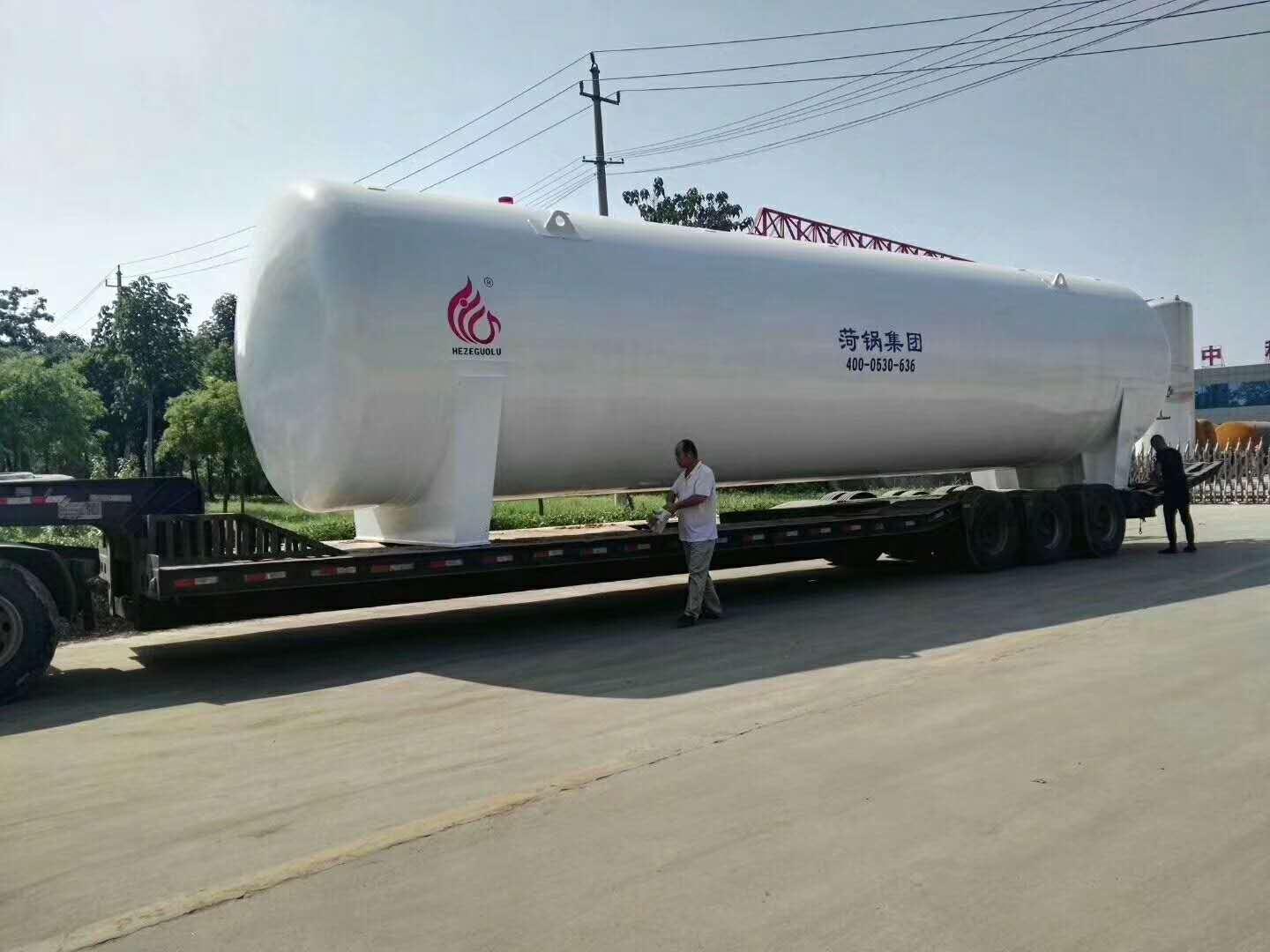
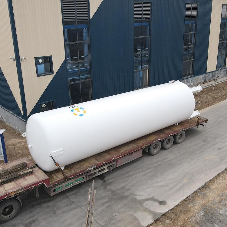
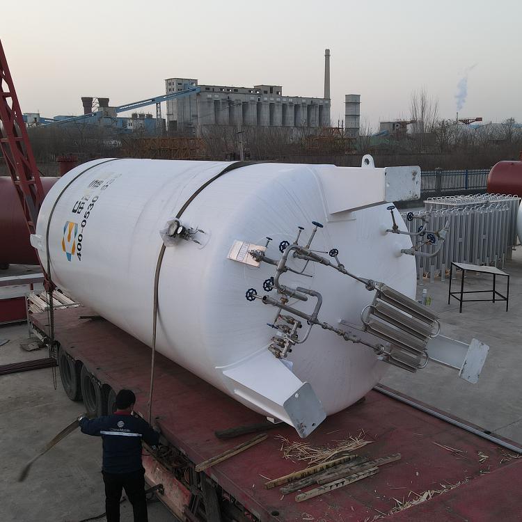
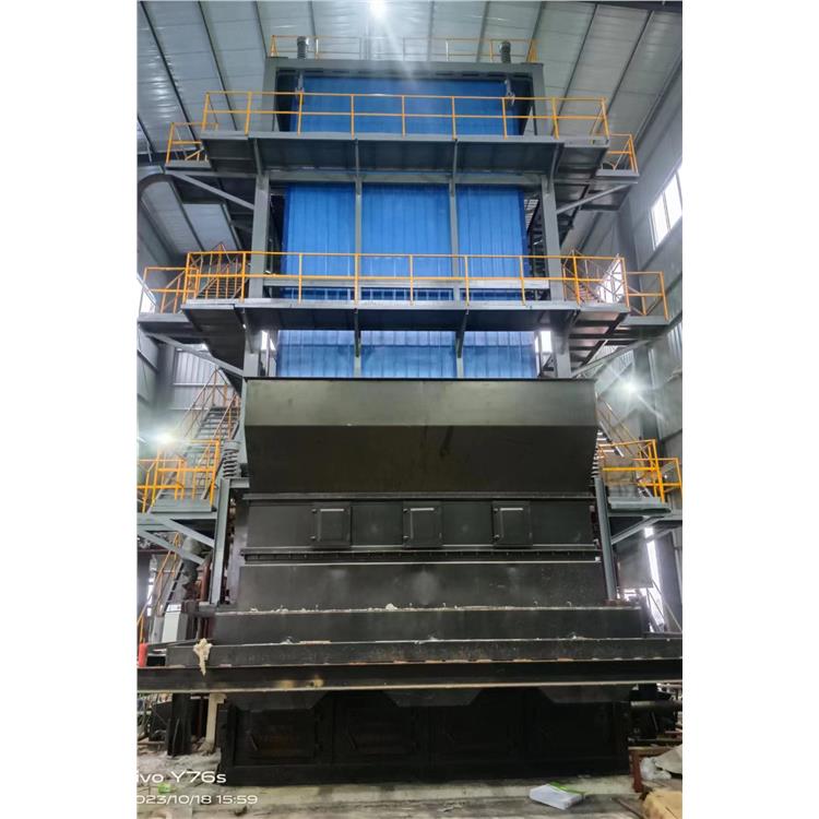
Liquefied Natural Gas (LNG) storage tank is a horizontal, double-layered cylindrical vacuum powder insulation structure, with the inner cylinder containingLNGMaterial:S30408The head is made of a standard elliptical head, with the outer cylinder facing the atmosphere, and the material isQ345RLow-alloy steel, an octagonal support structure is used between the inner and outer cylinders. Insulation thickness250mmThe inner and outer cylinder cavities are filled with thermal insulation material pearl sand and vacuumed, with the pressure between the inner and outer layers being absolute pressure ≤5PaThe factory vacuum level exceeds national standards, ensuring the evaporation rate specifications; the storage tank is equipped with a complete set of operational valves and gauges. These valves and gauges enable on-site observation of liquid flow and pressure, as well as level monitoring.
2Performance and structural parameters
LNG storage tanks are composed of the tank body, instruments, pipelines, valves, etc. These tanks are designed with both upper and lower liquid inlet methods, allowing for flexible selection based on actual conditions.
The inner tank of the Liquefied Natural Gas (LNG) storage tank is equipped with a safety system device featuring dual safety valves. Under normal operating conditions, one set is in operation while the other is on standby. Should the operating safety valve trip, the manual pressure relief valve is immediately opened to release pressure below the maximum working pressure of the tank. Simultaneously, the safety device is swiftly switched to the standby system via the manual handle, thereby effectively ensuring the tank's safety. This safety system device consists of safety valves, explosion-proof devices, vent valves, and three-way ball valves, not only reducing pipeline welding but also featuring excellent fire and static electricity prevention structures. Additionally, the safety relief openings on the housing are fully guaranteed to ensure the overall safety and reliability of the equipment. The low-temperature pipeline is centrally extracted for ease of operation and control, and the extraction outlet is designed with a Dura Tube structure to accommodate low-temperature requirements and minimize pipeline stress caused by thermal expansion and contraction, ensuring the tank's safety. The vacuum pump valve employs a triple-seal design.OFormed ring seal ensures reliable interlayer sealing, made entirely of stainless steel with compact size. The top design of the liquefied natural gas tank features a suspended structure for easy transportation, lifting, and installation. The unique manhole design ensures internal cleanliness when the container is sealed. Vacuum isolation valves and combined vacuum gauges are used on the liquefied natural gas tank for easy measurement of the interlayer vacuum level and maintenance, extending the tank's lifespan and improving its quality. The tank is equipped with a level gauge and pressure gauge for local display of liquid level and pressure. The interlayer insulation material is high-quality domestic pearl sand, with the following performance parameters of the pearl sand:
Serial Number | Index Name | Unit | Index |
1 | Loose Bulk Density | Kg/m3 | 50-60 |
2 | Particle size | mm | 0.1-0.2 Not less than80% |
3 | Thermal Conductivity (at atmospheric pressure),Temperature310-77k) | W/m.k.s | <0.026 |
4 | Moisture content(Weight) | % | <0.1 |
5 | Unexpanded Rate | % | ≤1 |
6 | Temperature | ℃ | -200℃~600℃ |
7 | PHValue | 6.5~7.5 |
Section 3: Inspection, Testing, and Acceptance
1Inspect the inner cylinder material, and it can be put into use only after passing the inspection.
2All welds are subject toGB150.1~150.4-2011Inspection of standards and drawings is conducted; upon passing inspectionA、BWeld seam equivalent100Radiation Detection %A、B、C、DWeld-like seam100Per cent permeability testing with a test report issued
3After the cylinder assembly is completed, proceed to...GB150.1~150.4-2011Standards and drawings require inspection of geometric dimensions, pipe end orientations, and shape deviations.
4After inspection, a pneumatic test is conducted and a pressure test report is issued. Upon passing the pneumatic test, a vacuum is drawn, and after the vacuum level meets the requirements, a helium leak test is performed.
5After interlayer leak detection passes, fill with pearl sand and then evacuate air, achieving the vacuum degree ofGB/T18442-2011Standard vacuum sealing requirements after closure.
IV. Technical Data
1After the contract is signed, the seller shall provide the buyer with the following technical information:
Certificate of Product Quality for Equipment1Set (supplied with equipment)
Including: Certificate of Material for Main Pressure Components, Bill of Materials, Structural Dimension Inspection Report, Inspection Plan, Product Compliance Certificate, Pressure Vessel Product Data Sheet, Welding Records, Non-Destructive Testing Report, Pressure Test Report, Supervision and Inspection Certificate for Special Equipment Manufacturing (Local Inspection Authority), Product Brand Copy
As-Built Drawings Various1Piece (supplied with the equipment)
Section 3: Strength Calculation Documents1Each (supplied with the equipment)
④ User Manual1Unit (provided with the equipment)
⑸ Equipment process diagram and basic reference diagram1Piece (Contract signed)7Available today (subject to availability)
⑹ Certificate of Conformity for accessories, Instrument Calibration Report 1Piece (supplied with the equipment)
5. Quality Assurance, After-Sales Service, Technical Support
1Equipment performance meets user requirements, ensuring normal operation within the process range.
2Valves and instruments on the storage tank come with a one-year warranty. Free service and repair are provided during the warranty period, along with free replacement of damaged parts. The equipment warranty period is from the date of delivery.12Month(s).
3During the warranty period, if any issues arise with our manufactured equipment on-site: In case of manufacturing defects, we will respond to the customer's formal notice within our regular working hours.2Hourly Response24Professional technicians will arrive on-site within hours to address the issue, service personnel will not leave the scene until the fault is resolved, and replacement parts are free during the warranty period; beyond the warranty, only cost-based charges apply.
4During the use of the equipment, if a malfunction occurs, the seller will first address the issue and then determine the responsibility, with the principle being to ensure the normal operation of the equipment.
Supplier offers lifetime technical consultation and answers users' questions at any time.

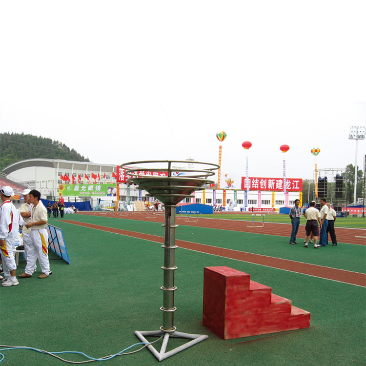
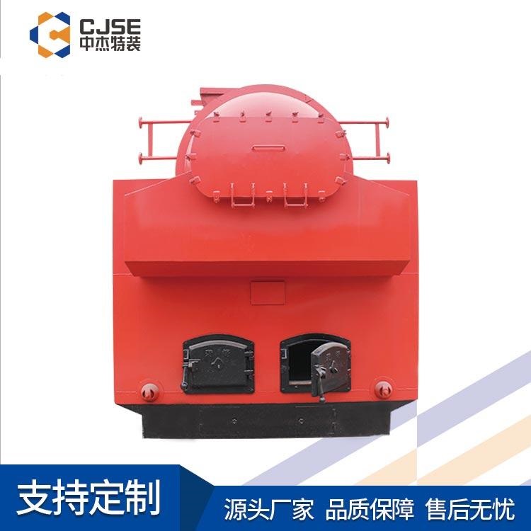
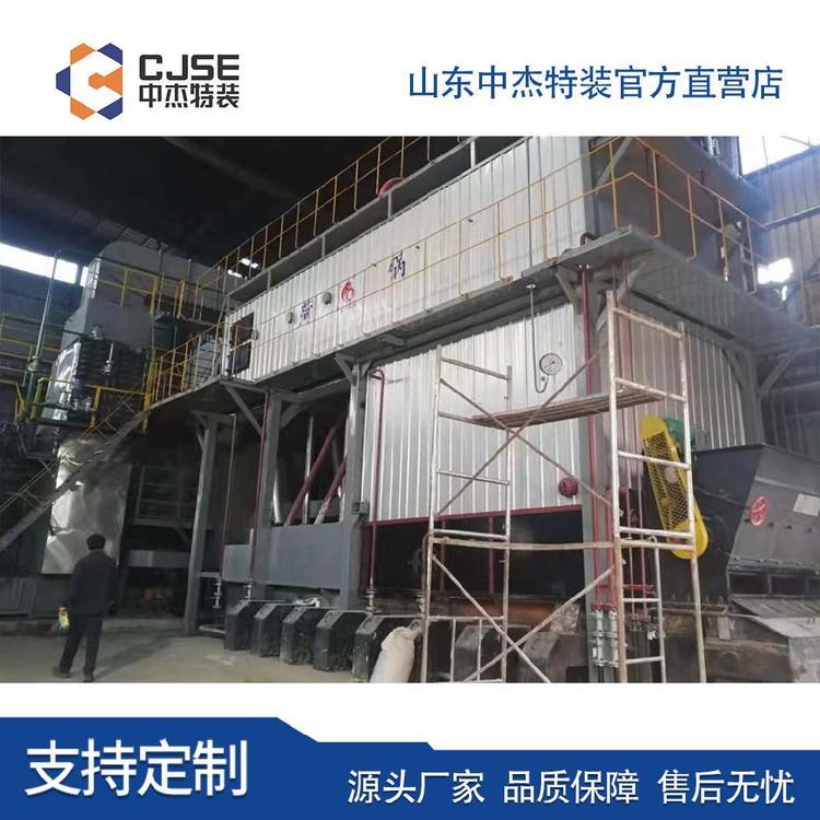
Liquefied Natural Gas (LNG) Storage Tank
Low-temperature Liquefied Natural Gas Storage Tanks, Manufacturer of Liquefied Natural Gas Storage Tanks:Heze Boiler Factory Co., Ltd., Manager Yu。
LNG above-ground storage tanks are available in five forms: the single-vessel tank is the most common, which comes in single-walled and double-walled versions. Due to safety and insulation concerns, single-walled tanks are not used for LNG storage. The outer shell of the double-walled single-vessel tank is made of ordinary carbon steel, unable to withstand the low temperatures of LNG or the gases at low temperatures, primarily serving to secure and protect the insulation layer. Single-vessel tanks are generally suitable for use in areas far from densely populated zones and less prone to catastrophic damage, as their structural characteristics require a larger safety distance and land area. The design pressure for single-vessel tanks is typically around kPa, with operating pressure at 12.5kPa. For large-diameter single-vessel tanks, the design pressure is correspondingly lower; according to BS7777 standards, such tanks have a design pressure less than 14kPa, which is difficult to achieve when the diameter is 70-80m, with the maximum operating pressure around 12kPa. Due to the lower operating pressure of the equipment, during unloading, the evaporated gas cannot be returned to the LNG vessel, necessitating an additional return gas fan. The lower design pressure makes the recovery and compression system for evaporated gases require more power, thereby increasing investment and operational costs. While the investment in single-vessel tanks is relatively low and the construction period shorter, leakage is a significant issue. According to regulations, the safety distance between single-vessel tanks is larger, and firebreaks must be set up, thereby increasing land and firebreak investment. No other critical equipment should be present nearby. Therefore, there is a higher requirement for safety inspections and operations.
Liquefied Natural Gas (LNG) Storage Tanks, Low-Temperature LNG Storage Tanks, Manufacturer of LNG Storage Tanks:
Huzhou Boiler Factory Co., Ltd., Manager Yu。
(1) A trench with a foundation of 1.5 em, length of 2014-7 Wanfang Data, electrical distribution, grounding electrode, Figure 3 Electrolytic ion grounding electrode, factory backfill clay, Figure 4 Electrolytic Yuzi grounding electrode installation, 330 cm in length and 20 tin in width. (2) Wipe the grounding electrode clean with a dry cloth, ensuring no oil stains; inject fresh water into the ion release holes at the top, middle, and bottom of the grounding electrode. (3) Mix the GAF powdered grounding modifier with water, then place it at the bottom of the trench. (4) Place the grounding electrode at a certain angle on the bottom of the trench, covering the top with the modifier. (5) Wrap the grounding electrode leads with insulating tape and connect them to the grounding main using a heat-welding method. 5 Static Grounding Setup: When LPG is injected into the storage tank, the liquid flow causes charge separation, and when the charges accumulate to a certain level, static discharge occurs. Since static discharge is completed within nanosecond time frames, its peak current can reach dozens of amperes, making the instantaneous power immense and the static discharge highly destructive. Methods to avoid static hazards: First, limit the speed of flow of flammable liquids to greatly reduce the generation and accumulation of static electricity; second, ensure proper static grounding. Static grounding provides a path for the release of static charges by grounding. The grounding circuit must be connected reliably; otherwise, spark discharges will occur at poor contacts. The specific method is to weld grounding bolts on the inner wall of the storage tank, connect them to the outer metal body via a 70 mm² insulated copper core wire to release static electricity. The static grounding connection is shown in Figure 5. Figure 5 Static Grounding Connection 6 Grounding Test Results: GB 50057-2010 Section 4.3.10 stipulates that the impact grounding resistance value at each grounding point should not exceed 30 ohms. GB 12158-2006 "General Guidelines for Preventing Static Electricity Accidents" Section 6.1.2 states that to dissipate static charges quickly in static hazard areas, all objects that are static conductors must be grounded, and the grounding resistance value of each dedicated static grounding body should generally not exceed 100 ohms. In areas with high soil resistivity, such as Zone A, the grounding resistance value should not exceed 1000 ohms. After the lightning protection grounding project is completed, the measured grounding resistance value is 0.8 ohms, and the grounding leads are well connected to the grounding main, meeting lightning protection grounding requirements.
LNG Storage Tanks, Low-Temperature LNG Storage Tanks, Manufacturer of LNG Storage Tanks:
Heze Boiler Factory Co., Ltd., Manager Yu。
Current transformer secondary circuit open circuit differential protection. Select through control words whether to lock the differential protection output when the current transformer secondary circuit is open circuit and the differential current is not significant. When the current transformer secondary circuit is open circuit and the differential current is not significant, the differential protection device emits an alarm signal to notify the dispatch personnel to shut down the transformer for maintenance by reversing the load. This can prevent the main transformer from tripping due to the secondary circuit open circuit of the current transformer. If the differential current increases to the set value of the open circuit differential protection (usually the transformer rated current, P), then the open circuit differential protection is activated. This ensures that the transformer differential protection operates, the main transformer trips, and the protective device can correctly disconnect the fault current to prevent the accident from escalating. This can be considered a compromise solution that balances the advantages and disadvantages of the first two methods, achieving a good effect. For the No. 1 110 kV substation's No. 3 main transformer (capacity 63 MVA, voltage ratio 110 kV/10.5 kV, connection type YNdll, primary current transformer ratio 600 A, secondary current transformer ratio 4000 A, the differential protection set values are as follows: differential quick-break current setting, .. = 4.4 (A), differential protection start setting, .. = 0.28 (A), ratio制动 coefficient setting K = 0.5, second harmonic braking coefficient 0.15, open circuit differential protection setting 0.8. One day at 6:42, an alarm was triggered at the No. 1 substation's back-end, indicating that the secondary circuit of the No. 3 main transformer's differential protection current transformer was open circuit, with a sudden change in current of 0.08 A and an A-phase differential current of 0.056 A. After contacting the dispatch personnel to reverse the load and shut down the power, the equipment was inspected and found to be loose terminal strips on the SF6 enclosed switchgear. After tightening the terminal strips, the fault was eliminated.


知名LNG储罐生产厂家-正品LNG储罐规格-专业LNG储罐型号-正品LNG储罐批发