


LNG Storage Tanks | Manufacturer of LNG Storage Tanks--Heze Boiler Factory Co., Ltd.

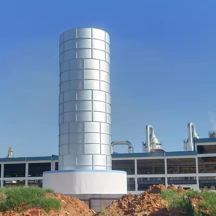
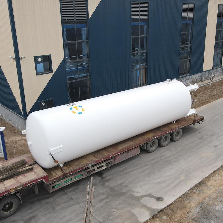
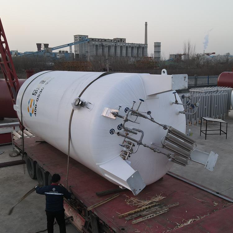
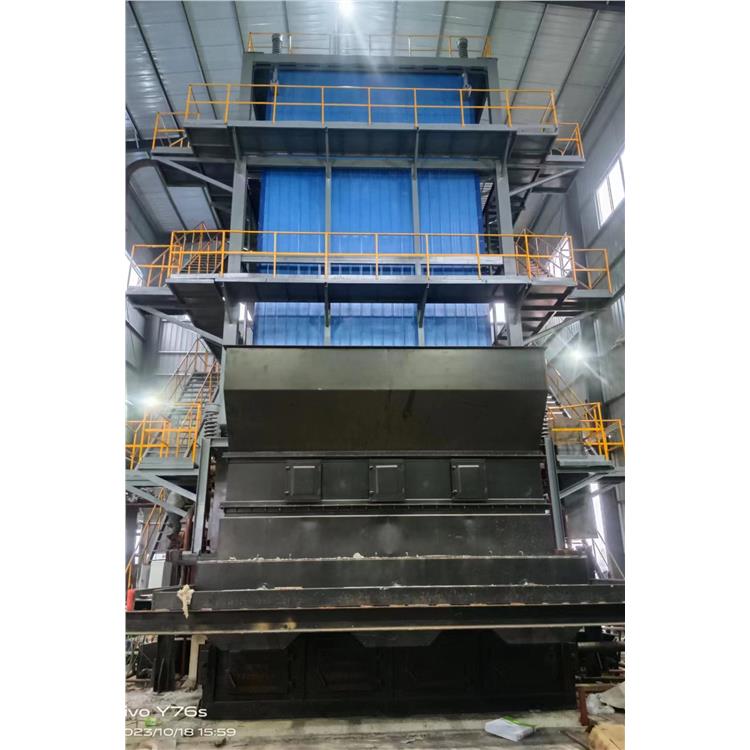
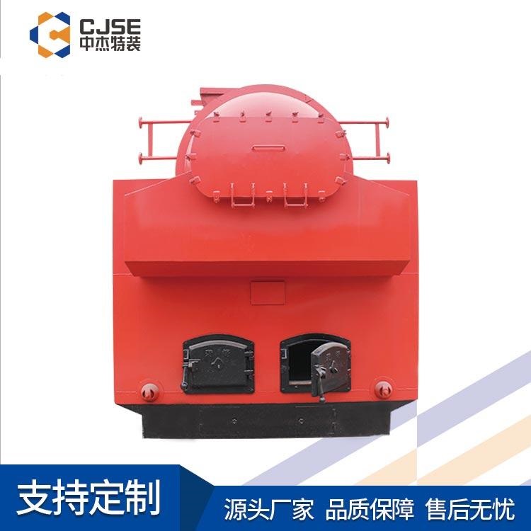
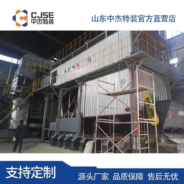
LNG storage tanks are specialized equipment designed for storing liquefied natural gas.TwoType pressure vessels, completed with on-site inspection by the Technical Supervision Bureau, issuance of pressure vessel inspection certificates, and processes such as external rust removal and painting. The liquefied gas storage tank undergoes rigorous quality assessment for the material, dimensions, weld quality, operating quality, installation quality, internal equipment, and safety accessories of the pressure components. Widely used in industries such as industrial gases and gas fuels, including units with high gas consumption such as machinery, chemicals, and metallurgy, it serves as a centralized gas supply system.The mostHigh-quality equipment. Features include long service life, small footprint, easy operation, and centralized control. The gas leaked from the LNG tank is also very cold, and contact with the skin can cause burns similar to blisters, known as low-temperature burns. Natural gas is an asphyxiant. The oxygen content in the atmosphere is approximately 21%, and when the oxygen content in the air falls below 18%, it can cause human asphyxiation.

LNG Storage Tank Operation Procedure:
Wear antistatic suits, shoes, helmets, etc., and place devices prone to static electricity, such as cell phones and computers, in a safe area.
Check the tank's thermometer, level gauge, pressure gauge, flammable gas alarm, and safety valve for proper functioning.
All valves of the tanks to be pressurized are to be confirmed closed, except for the root valve and the emergency shut-off valve.
4. The lower tank inlet valve and the增压 liquid and vapor valves are open, as well as the valves on both sides of the booster vaporizer.
5. Open the low-temperature cutoff valve before the vaporizer, the ambient temperature flange ball valve after the vaporizer, and all valves required to be opened in the pressure regulation system.
6. A single storage tank is sufficient to meet the gas supply requirements when the flow rate is less than 1000Nm3/h up to 2000Nm3/h.
7. When the tank pressure rises above 0.15 MPa higher than the outlet pressure, slowly open the liquid outlet valve and start supplying gas.
8. During operation, LNG tanks must maintain a liquid level upper limit of less than or equal to 90% and a lower limit of greater than or equal to 15%.
8. The on-duty staff must frequently inspect the gas supply, monitor the liquid level and pressure changes of the storage tank, ensuring at least three records per day.
9. Regularly inspect the tank, welds, valves, etc., and take timely measures to address any gas leaks to ensure LNG meets production requirements.
Maintain and repair
Routine Maintenance
The housing must not be subjected to any impact and operations should be performed according to regulations. External valve and pipe fittings should be kept clean and intact, with valves that operate smoothly and are regularly inspected as per regulations. Under normal use, an annual check and maintenance of all valves, pipe fittings, and instruments should be conducted, and replacement of wearables (such as valve seals) should be done promptly.
2. Insulation performance maintenance
One of the key requirements for low-temperature liquid storage tanks is excellent insulation performance, with the quality of vacuum being crucial to the insulation.
Once the vacuum of the tank is compromised, it cannot store low-temperature liquids. Therefore, special attention must be given to protecting the tank's vacuum. The explosion-proof device and the vacuum valve on the tank shell are directly connected to the vacuum jacket. The device must not be tampered with unless the jacket vacuum is not damaged, or it is not necessary to replenish and re-vacuum with mica sand. The vacuum valve is sealed with lead at the factory and must not be moved arbitrarily; otherwise, it will damage the tank's vacuum.
The tank shell is an external pressure vessel, subjected to atmospheric pressure. It is strictly prohibited to strike or bump it to prevent damage to the shell and affect the vacuum degree.
3. Inspect
(1) Routine inspection
1) Is the valve in the correct open/close position?
2) Accuracy and reliability of pressure gauge and differential pressure (level) meter measurements.
3) Pipeline and valve for leakage and blockage issues.
4) If the container pressure reaches the set pressure of the safety valve and the valve does not activate, the safety valve's set pressure should be immediately adjusted to ensure the tank's safety.
5) Check if the turbocharger connection flange bolts are loose and if there is any deformation in the pipes.
(2) Regular maintenance
1) The pressure gauge is calibrated annually.
2) The safety valve is inspected annually.
3) Measure vacuum annually.
4) Pyrometers (customer-purchased, not within the supply scope) should be calibrated according to their instruction manual prior to each measurement.
5) Tanks' grounding resistance should be tested annually; less than 10Ω is considered合格. If greater than 10Ω, the connection status should be checked promptly.
(3) Vacuum Level Inspection and Re-evacuation
The tank's vacuum level is measured once a year. To measure, simply unscrew the protective cap of the metal thermocouple tube, insert the plug of the thermocouple vacuum gauge, and you can determine the interlayer vacuum level.
After several years of use, the vacuum level in the tank may drop to 65Pa, necessitating a re-evacuation. To enhance insulation properties, first, drain the liquid inside the tank, then heat and blow with dry, oil-free air or nitrogen at 80-100℃ until it returns to normal temperature. Connect the vacuum piping, start the pump to remove moist air from the pipes, and then open the vacuum valve to evacuate.
To shorten the vacuuming time, the container can be heated using dry, oil-free air below 100℃. The vacuum degree of the annular seal should be ≤3Pa. If necessary, the user may contact the manufacturer regarding vacuuming matters, and both parties can agree on the specific process for re-vacuuming.
4. Fault Handling
(1) Safety Valve Fault Handling
1) Safety valve leakage
The valve disc and seat sealing surface may experience leakage beyond the permissible level under operating pressure, the possible causes being:
There is debris on the sealed surface.
Prior to installation, if the cleaning with compressed air is not thorough, or if solid impurities are present in the fluid during the trial run, or if the necessary actions are not performed, debris may become trapped between the valve seat and the sealing surface. If it's easy to remove the debris, do so manually. However, if there is still leakage after removal, consider the following reasons: it may be damage to the valve seat and its sealing surface; or the debris may have become embedded between the valve seat and sealing surface. If this situation is difficult for the user to handle, return it to the manufacturer for repair.
② Internal Pipeline Force
a) Human Factors
During the process of installing the safety valve on the pipeline, if it is forcibly rotated, the valve seat may rotate, and the position of the adjustment ring of the safety valve may change, or the sealing surface may be forcibly worn. A decrease in operational performance may occur. In such cases, depending on the situation, it can be handled on-site by the user or returned to the factory for processing, but it is necessary to fully grasp the situation and make a quick judgment.
b) Internal Force Factors
The adverse effect of welding residue's force within the pipeline on the safety valve. The issue occurring at this time is almost completely consistent with the aforementioned situation. Therefore, it is crucial to fully consider the absorption of the force within the pipeline during pipeline installation. This point is of utmost importance.
c) The set pressure of the safety valve is too close to the normal operating pressure of the equipment, resulting in an excessively low sealing face pressure. This makes it more prone to leakage when the safety valve is subjected to vibration or fluctuations in the medium pressure. Under the condition of meeting the strength requirements, the set pressure of the safety valve should be appropriately increased during design.
③Spring relaxation reduces the setting pressure, causing the safety valve to leak.
The primary cause of spring relaxation may be that after the safety valve has been calibrated, the adjustment screw has not been securely tightened, causing it to loosen during equipment operation, resulting in spring relaxation, a decrease in pre-tension, and premature opening of the safety valve. A recalibration of the safety valve is recommended.
2) Inflexible operation of the safety valve opening and closing
The reason may be:
Improper adjustment of the safety valve's regulating ring leads to an extended opening process or delayed return to the seat. It should be readjusted. By adjusting the lower regulating ring, increase the return seat pressure.
②The exhaust pipe of the safety valve has excessive resistance, causing significant back pressure during discharge, which results in insufficient opening height of the safety valve. By changing the exhaust pipe of the safety valve to a straight-through design and removing the middle bend, the safety valve will function normally.
3) Safety valve frequent chattering or trembling
The reason may be:
The relief valve's discharge is excessive. The rated discharge of the selected relief valve should be as close as possible to the equipment's necessary discharge.
② The imported pipeline diameter is too small or has too much resistance.
③ Excessive resistance in the exhaust pipe causes high back pressure during emission. Reduce the resistance of the exhaust pipe.
④Improper adjustment of the adjusting ring causes excessive return seat pressure. The position of the adjusting ring should be re-adjusted.
4) Operation of Three-way Valve A-5 during the replacement of the safety valve
① Two safety valves operate simultaneously during normal operation, with both channels open at the same time, as shown in Figure 1.
②When replacing the safety valve, rotate the handle 90 degrees (as shown in Figures 2 and 3), close the side channel being replaced, and empty the remaining medium inside the channel, then replace the safety valve.


哪里有卖LNG储罐供应商-优质LNG储罐生产-专业定做LNG储罐规格-供应LNG储罐加工厂