


Operation Instructions
1. Utilize Security Management
(1) The user unit shall apply for and obtain the "Special Equipment Operation Registration Certificate" from the department responsible for special equipment operation registration at the location within 30 days before or after the product is put into use.
(2) Users shall comply with the relevant requirements of the "Special Equipment Operation and Management Regulations" to ensure the safety of this product. This includes appointing a safety management supervisor and staff, establishing safety management systems, formulating operational procedures, and conducting inspections.
2. Pre-Use Preparation
Tanks and associated piping are installed and positioned. Upon passing the acceptance inspection, pre-use preparations are made.
Tanks must be purged with dry nitrogen and pre-cooled with liquid nitrogen prior to first use. The purge pressure should not be less than 0.2 MPa.
Prior to blowing, loosen the connections at both ends of the differential pressure (level) gauge, and fully open the combination valve A9 of the differential pressure (level) gauge. Check if there is any moisture in the exhaust air flow. If moisture is present, continue blowing until it stops. Tighten the connections at both ends of the differential pressure (level) gauge, close the balancing valve, and ensure the differential pressure (level) gauge is in normal operating condition.
Prior to the first filling of the tank with LNG, the liquid nitrogen or nitrogen inside the tank should be replaced with LNG gas. First, open the drain valve A-6 to vent the nitrogen, then close the valve. Open the exhaust valve A-12 and transfer LNG gas from the LNG tank container to the tank through the unloading platform. When the tank pressure reaches 0.1-0.2 MPa, close the exhaust valve A-12, stabilize for 3 minutes, and then open the drain valve A-6 to vent. Repeat this process 2-3 times, and the replacement is complete. A combustible gas detector or air vent sample can be used for ignition tests to check the replacement extent.
During the first LNG filling, the tank should be pre-cooled or check the pre-cooling status of the tank previously. The liquid filling rate must be strictly controlled and operated slowly. First, slowly open the upper filling valve A-2, and transfer the LNG from the tanker to the tank via the unloading platform. Due to the lag in vaporization when LNG is transferred to the tank, closely monitor the rate of pressure increase inside the tank. Ensure the liquid filling amount is minimal. When the pressure reaches 0.3 MPa, open the gas exhaust valve A-12 to depressurize, and close the upper filling valve A-2 if necessary. Continue with a cycle of filling and exhaust to pre-cool the tank. After a period of controlled liquid filling, once the tank pressure stabilizes and the liquid level gauge indicates a certain level, gradually increase the opening of the upper filling valve A-2 and open the lower filling valve A-1.
3. Initial Filling Operation for Storage Tank
(1) Open the liquid inlet valves A-2 and A-1 at the top and bottom simultaneously for filling. During the filling process, monitor the differential pressure (level) gauge readings. Open the full indicator valve A-4, vent the gas in the storage tank, and immediately close valve A-4 when LNG gas is discharged.
(2) When filling to over 50% of the tank's capacity, the lower liquid inlet valve A-1 should be closed.
(3) When the tank is filled to over 85% of its capacity, close valve A-2 to stop filling and wait for 5 minutes to allow the liquid level in the container to stabilize. Then, reopen valve A-2 to continue filling and open valve A-4 to indicate fullness. Close valve A-4 and valve A-2 immediately when liquid starts to flow out of A-4, and stop filling.
4. Tank Refueling Operation Procedure
(1) Upon the first formal filling, the gas phase pressure inside the tank should be as low as possible during subsequent refills.
(2) Fill both the upper and lower sections simultaneously. When the differential pressure (level) gauge indicates approximately 50% of the tank's volume, close the lower inlet valve A-1. When filled to about 85% of the tank's volume, close the upper inlet valve A-2, stop filling for 5 minutes to allow the liquid level in the container to stabilize, then reopen the upper inlet valve A-2 to continue filling and open the full indicator valve A-4. Continue filling until liquid begins to drain from the full indicator valve A-4, then close the full indicator valve and simultaneously close the upper inlet valve A-2, and stop filling.
(3) Monitor the pressure gauge and differential pressure (level) gauge during filling. (If the pressure rises above the filling transfer pressure or near the safety valve pressure, the exhaust valve A-12 must be opened to release a sufficient amount of gas from the tank to relieve pressure.)
(4) Fill out the operation record form.
5. Tank Pressurization Operation Procedure (Valves and equipment for this stage are provided and installed by the owner)
Using a supercharger can increase the pressure inside the tank. The boost pressure is controlled according to the draining requirements and must not exceed the tank's maximum working pressure. The boost system of this tank is controlled by a pressure regulating valve, with the product pressure adjustment range being 0.2 to 0.8 MPa. The boost operation procedure is as follows:
Check if the pressure gauge is in working condition.
(2) Confirm the boost system pressure regulator is turned on.
(3) Gradually open the shutoff valve.
(4) When stopping the fluid discharge, close the shutoff valve to prevent an increase in tank pressure.
(5) Important Notes:
1) During operation, the LNG tank must maintain a liquid level of ≥15%.
2) When operating the boost system, safety should be a priority, and strict monitoring is required. Unauthorized personnel must not leave the site.
6. Tank Pressure Reduction Procedure
Open valve A-12 to reduce the gas phase pressure inside the storage tank to no more than the pressure set by the pressure regulator, then close valve A-12.
7. Tank Discharge Operation Procedure
Check that the tank's pressure gauge, differential pressure (level) gauge, flammable gas detector, and safety valve are operating normally.
(2) Inspect that the pipeline valves, pressure gauges, and safety valves are operating normally.
(3) Prepare all explosion-proof tools and wear protective gear.
(4) Inspect the IV line and open drain valve A-6.

Maintain and service
Routine Maintenance
The housing must not be subjected to any impact; operations should be carried out in accordance with regulations. External valve fittings should be kept clean and intact, with valves that operate smoothly. Regular calibration should be conducted as per regulations. Under normal use, a full inspection and maintenance of all valve fittings and instruments should be performed annually. Replacement of consumable parts (such as valve seals) should be timely.
2. Insulation Performance Maintenance
One of the key requirements for low-temperature liquid storage tanks is excellent insulation performance, with the quality of vacuum being crucial to the insulation.
Once the vacuum level of the storage tank is compromised, it cannot store low-temperature liquids. Therefore, special attention should be given to protecting the vacuum level of the tank. The explosion-proof device of the tank's shell and the vacuum valve are directly connected to the vacuum interlayer. The device should not be tampered with unless the vacuum level in the interlayer is not damaged or there is no need to replenish and re-evacuate with pearly sand. The vacuum valve is sealed with lead at the factory and must not be moved arbitrarily; otherwise, it will damage the vacuum level of the storage tank.
The tank shell is an external pressure vessel, subjected to atmospheric pressure, and is strictly prohibited from being struck or bumped to prevent damage to the shell and affect the vacuum level.
3. Inspect
(1) Routine inspection
1) Is the valve in the correct open/close position?
2) Accuracy and reliability of pressure gauge and differential pressure (level) meter measurements.
3) Check for any leaks or blockages in pipes and valves.
4) If the container pressure reaches the set pressure of the safety valve and the valve does not activate, the safety valve's set pressure should be immediately adjusted to ensure the tank's safety.
5) Are the turbocharger flange bolts loose, and is there any deformation in the pipes?
(2) Regular maintenance
1) The pressure gauge is calibrated annually.
2) The safety valve is inspected annually.
3) Measure vacuum level annually.
4) Thermocouple vacuum gauges (purchased by the user, not within the supply scope) should be calibrated according to the instructions before each measurement.
5) Inspect the storage tank's grounding resistance annually; a resistance less than 10Ω is considered acceptable. If greater than 10Ω, the connection status should be checked promptly.
(3) Vacuum Level Inspection and Re-evacuation
The tank's vacuum level is measured once a year. To measure, simply unscrew the protective cover of the metal thermocouple probe and insert the plug of the thermocouple vacuum gauge, then you can determine the interlayer vacuum level.
After several years of use, the vacuum level in the tank may drop to 65Pa, necessitating a re-evacuation to enhance insulation properties. Prior to re-evacuation, the liquid inside the tank should be fully drained, and then heated to 80-100°C using dry, oil-free air or nitrogen to blow out until it returns to normal temperature. Connect the vacuum piping, start the pump to remove the moist air from the pipe, then open the vacuum valve to evacuate.
To reduce the vacuuming time, the container can be heated using dry, oil-free air at temperatures below 100°C. The interlayer sealed vacuum degree should be ≤3Pa. If necessary, users can contact the manufacturer for vacuuming matters and agree on the specific process for re-vacuuming.
4. Fault Handling
(1) Safety Valve Troubleshooting
Safety valve leakage
The valve disc and seat sealing surface may experience leakage beyond the permissible level under operating pressure, the possible causes being:
There is debris on the sealed surface.
If the valve is not properly cleaned with compressed air before installation, or if solid impurities enter during the trial run, or if it is necessary to perform the required actions, debris may become trapped between the valve seat and the sealing surface. If it's easy to remove the debris, do so manually. However, if there is still leakage after removal, consider the following reasons: the valve seat and sealing surface may be damaged; or debris may be embedded between the valve seat and the sealing surface. If this situation is difficult for the user to handle, return it to the manufacturer for repair.
② Internal Pipeline Force
a) Human Factors
During the process of installing the safety valve on the pipeline, if it is forcibly rotated, the valve seat may rotate as well. In this case, the position of the safety valve adjustment ring may change, or the sealing surface may be worn down forcibly. A decrease in operational performance may occur. If this situation arises, depending on the circumstances, it can either be handled at the user's site or sent back to the factory for processing. However, making a prompt and accurate judgment of the situation is essential.
b) Internal Force Factors
The adverse effect of welding residue's force within the pipeline on the safety valve. The issue occurring here is almost entirely consistent with the aforementioned situation. Therefore, it is crucial to thoroughly consider the absorption of the force within the pipeline during installation.
c) The set pressure of the safety valve is too close to the normal operating pressure of the equipment, resulting in a low sealing ratio pressure on the sealing surface. This makes it more prone to leakage when the safety valve is subjected to vibration or fluctuations in the medium pressure. Under the condition of meeting the strength requirements, the set pressure of the safety valve should be appropriately increased during design.
③Spring relaxation reduces the set pressure, causing the safety valve to leak.
The primary cause of spring relaxation may be that after the safety valve has been checked, the adjustment screw was not properly tightened, leading to loosening during operation, resulting in spring relaxation, decreased pre-tension, and premature opening of the safety valve. A re-check of the safety valve is recommended.
2) Inflexible safety valve operation
The reason may be:
①Improper adjustment of the safety valve's regulating ring causes the opening process to prolong or the return to be slow, which should be adjusted again. By adjusting the lower regulating ring, increase the return pressure.
②The exhaust pipe of the safety valve has excessive resistance, causing significant back pressure during discharge and insufficient opening height for the safety valve. To normalize the safety valve's operation, the exhaust pipe should be modified to be a straight-through design, removing the middle bend.
3) Safety valve frequent chattering or vibration
The reason may be:
The safety valve's discharge is excessive. The rated discharge of the selected safety valve should be as close as possible to the equipment's required discharge.
② The imported pipeline diameter is too small or has excessive resistance.
③ Excessive resistance in the exhaust pipe causes high back pressure during emission. Reduce the resistance of the exhaust pipe.
④Improper adjustment of the regulating ring causes excessive return seat pressure. The position of the regulating ring should be realigned.
4) Operation of three-way valve A-5 during replacement of the safety valve
①Two safety valves operate simultaneously during normal operation, with both channels open at the same time, as shown in Figure 1.
②When replacing the safety valve, rotate the handle 90 degrees (refer to Figures 2 and 3), close the side channel being replaced, and empty the residual medium inside the channel, then replace the safety valve.


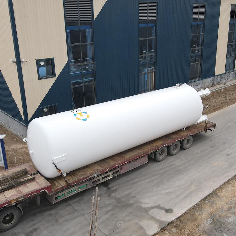
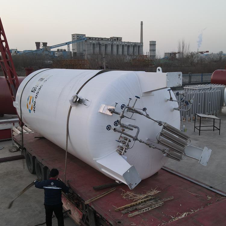
现货LNG储罐制作-正品LNG储罐多少钱-正规LNG储罐生产厂家-现货LNG储罐出售