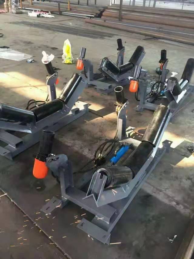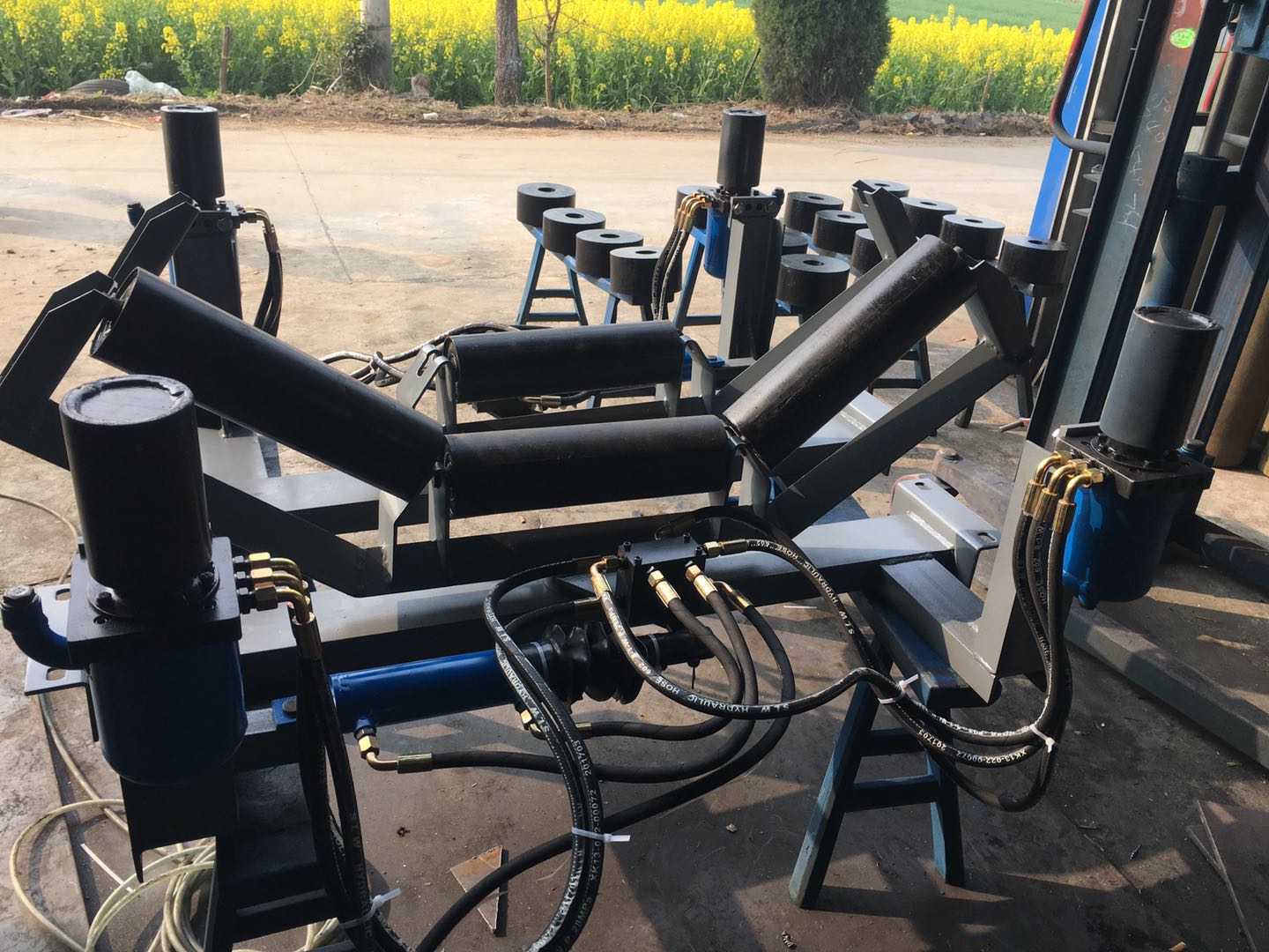
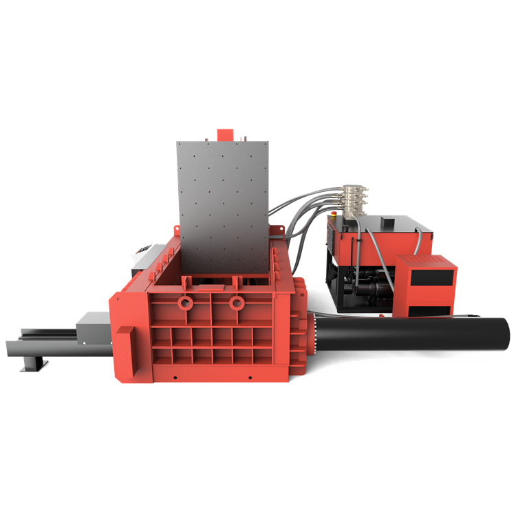
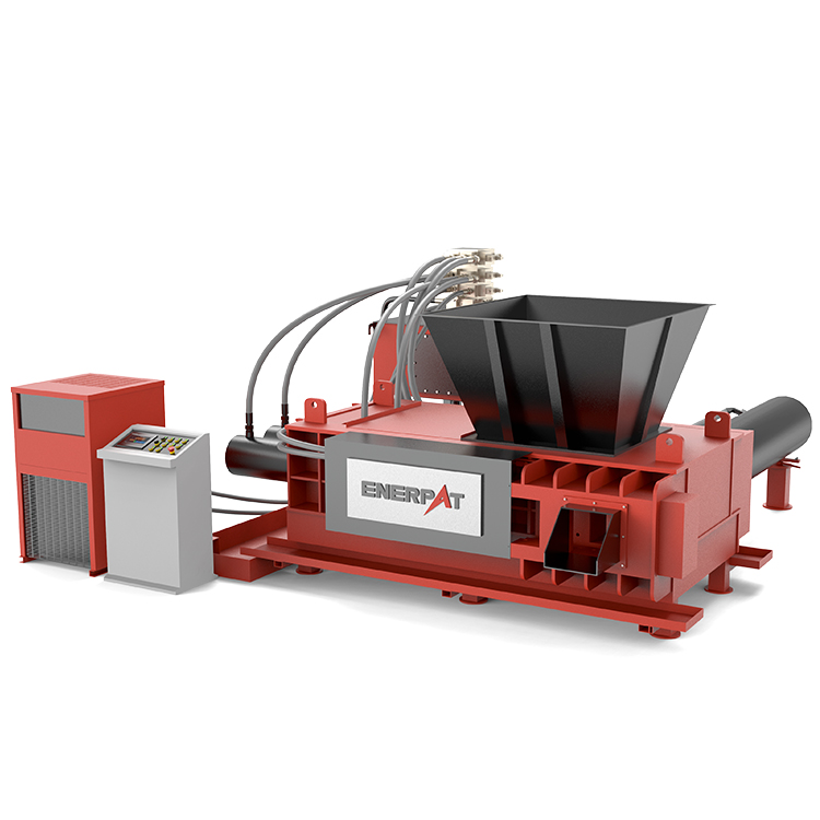


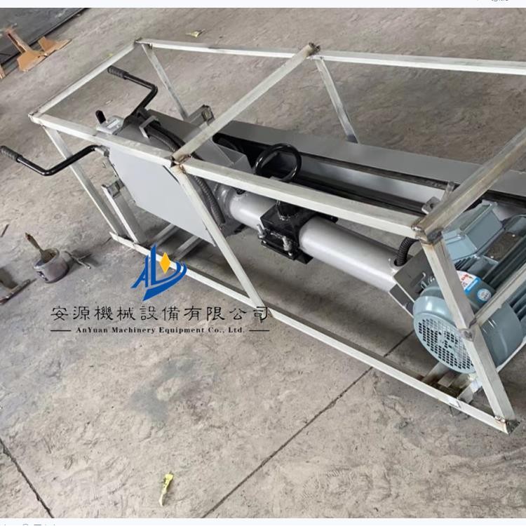
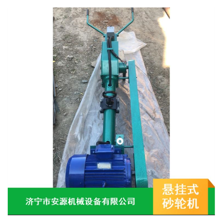
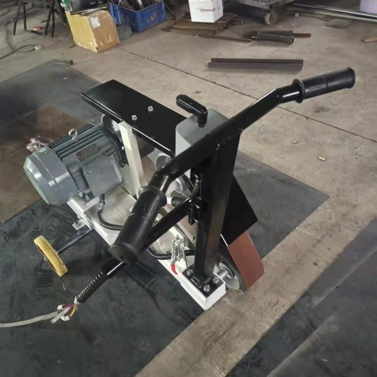
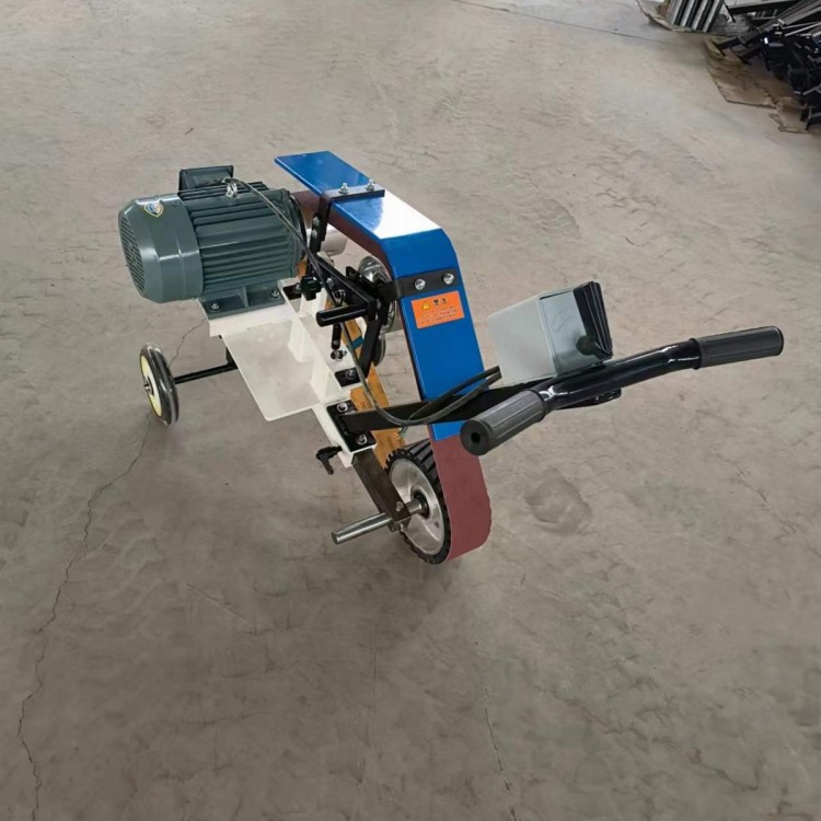
Hydraulic Automatic Tractive Anti-Deviation Corrector, Belt Anti-Drift Device

| Referring to the attached illustration, on rack l, two vertical drive-checking wheels 3 are installed on both sides of a set of aligning idlers 2 at the same height. The shaft of the drive-checking wheels 3 is connected to the power input shaft of the oil pump 4. Two fixed brackets 5 are used to secure the drive-checking wheels 3 on both sides of the rack l, with a compound hydraulic cylinder 6 set between the aligning idlers 2 and the left fixed bracket 5. The tail of the compound hydraulic cylinder 6 is hinged to the fixed bracket, and the piston rod of the compound hydraulic cylinder 6 is pivotally connected to the rotating part of the idler frame of the aligning idlers 2 on the left side. Oil pipes connect the oil outlet of the oil pump 4 to the oil outlet of the tail of the compound hydraulic cylinder 6. As shown, when the belt 7 runs forward, if the belt 7 runs off to the left, it triggers the left drive-checking wheel 3, causing the left oil pump to quickly output pressure oil. This oil enters the rodless cylinder of the cylinder through the oil path assembly block of the compound hydraulic cylinder 6, pushing the piston and piston rod. The hydraulic oil in the rod cylinder returns to the oil tank of the compound hydraulic cylinder through the oil path assembly block, causing the piston rod to extend rapidly, pushing the aligning idler 2 to rotate clockwise (i.e., the left side of the aligning idler moves forward), driving the belt 7 to run to the right and remain centered. When the belt 7 runs off to the right, it triggers the right drive-checking wheel 3, causing the right oil pump to output pressure oil. This oil enters the rod cylinder of the cylinder through the oil path assembly block of the compound hydraulic cylinder 6, pushing the piston, causing the piston rod to retract. The hydraulic oil in the rodless cylinder returns to the oil tank of the compound hydraulic cylinder 6 through the oil path assembly block, causing the piston rod to retract rapidly, pulling the aligning idler 2 to rotate counterclockwise (i.e., the left side of the aligning idler moves backward), driving the belt 7 to run to the left and remain centered. Selection Notes: 1. The hydraulic alignment device has two series: (1) Type I series, suitable for TD75 belt conveyors. (2) Type H series, suitable for DTII belt conveyors. 2. According to the upper and lower layers of the belt of the belt conveyor, it is divided into upper belt alignment device and lower belt alignment device. 3. According to the one-way and two-way transport of the belt conveyor, it is divided into one-way alignment device and reversible alignment device. 4. Specification Parameters: Selection: DTII belt conveyor users must provide the middle frame and roller part number or roller diameter and roller slot angle of the belt conveyor installation location. TD75 belt conveyor users only need to provide the belt width of the belt conveyor. 5. To make the alignment device easy to use and reliable in performance, it is recommended that users choose the special aligning idler matched by our factory. Installation: 1. The hydraulic alignment device should be installed at the location where the belt needs to be corrected. Please refer to the user manual before installation. 2. The hydraulic oil used by the hydraulic alignment device is HM-32, with oil filtration accuracy of 209Pm. 3. To make it easy and quick to add oil |