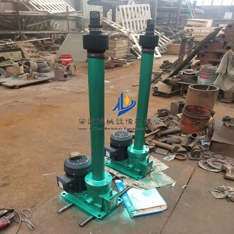


DT/DTZ Type Electric Push Rod, Electro-Hydraulic Push Rod, Electric Telescopic Push-Pull Rod
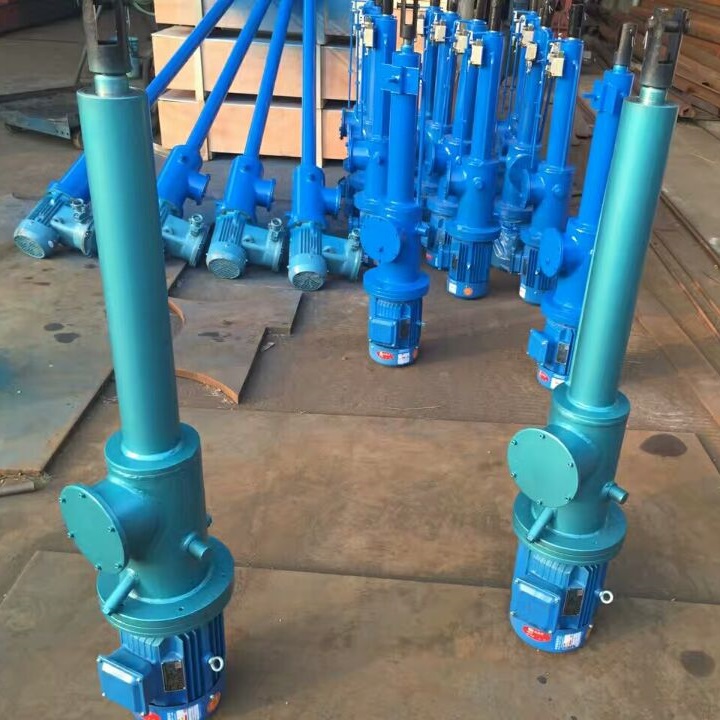
An electric actuator is a reciprocating linear motion actuator that, with the aid of other rods, can also perform rotation and swing. It is widely used for its advantages such as light weight, high thrust and pull force, low noise, low energy consumption, easy installation and maintenance, operable individually, and capable of remote centralized control. It is extensively applied in metallurgy, power, coal, machinery, chemical industries, particularly suitable for long-distance, high-altitude, and hazardous environments. It can replace hydraulic and pneumatic devices for centralized or automatic control.
1. Structure
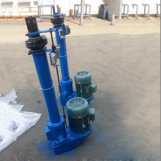
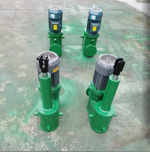
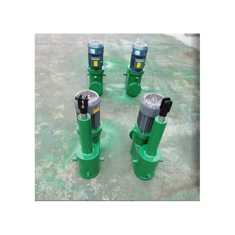
The electric actuator is composed of a drive motor, a reduction gear, a screw, a guide sleeve, a push rod, a sliding seat, a spring, a housing, a connector, and a stroke switch. It features a compact structure, sensitive operation, and easy installation.
2. Structural Diagram
1. Electric Motor 2. Small Gear 3. Large Gear 4. Left and Right Travel Switches 5. Sliding Seat
6. Lever 7. Nut 8. Spring 9. Screw Rod 10. Guide Sleeve Assembly
11 Guide Rails, 12 Push Rods, 13. Connectors
WorkerOperation Principle
Electric push rods are powered by electric motors, which, after undergoing speed variation, drive the screw spiral pair to produce linear motion. Since the inner tube of the push rod and the nut are fixed, the equipment is connected to the inner tube via a joint for operation. The motion of extension or retraction is produced by the forward and reverse rotation of the motor, which is the working principle of the electric push rod. Under reasonable electrical power matching, the size of the force exerted by the electric push rod is determined by the spring. The electric push rod drives the equipment, but may be obstructed during operation due to various factors or when the push rod reaches the ends. Location, the inner tube of the push rod remains stationary while the screw can still rotate, then the screw has potential In the opposite direction of the push rod's inner tube, as the structure shows, the screw rod drives the sliding seat to overcome the set spring force, actuating the lever, pressing the limit switch, and shutting off the power, thereby serving as a protective measure. Since the switch is prone to damage, our company has specifically developed a mechanical protection device in conjunction with the structure of the electric push rod. It has a high sensitivity, and during the factory debugging, the mechanical protection device exerts a greater force than the electrical protection.Approximately 500N, with this, the two sets of protection devices can effectively and reliably safeguard the push rod itself and the connected equipment.