


1. Preparation Before Operation
Product Details Image
1.1 The operator must operate in accordance with the instructions in this manual and any related documents.
1.2 Prior to formal operation, the entire system is purged and replaced using dry CO2 gas, with the purity of the purge/replacement gas being no less than that of the filling medium.
Product Details Image
Primary Variable, Variable 3, Variable 2, Variable 1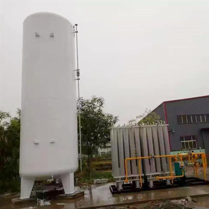
[Title]
Primary Variable | Variable 1
Product Details Image
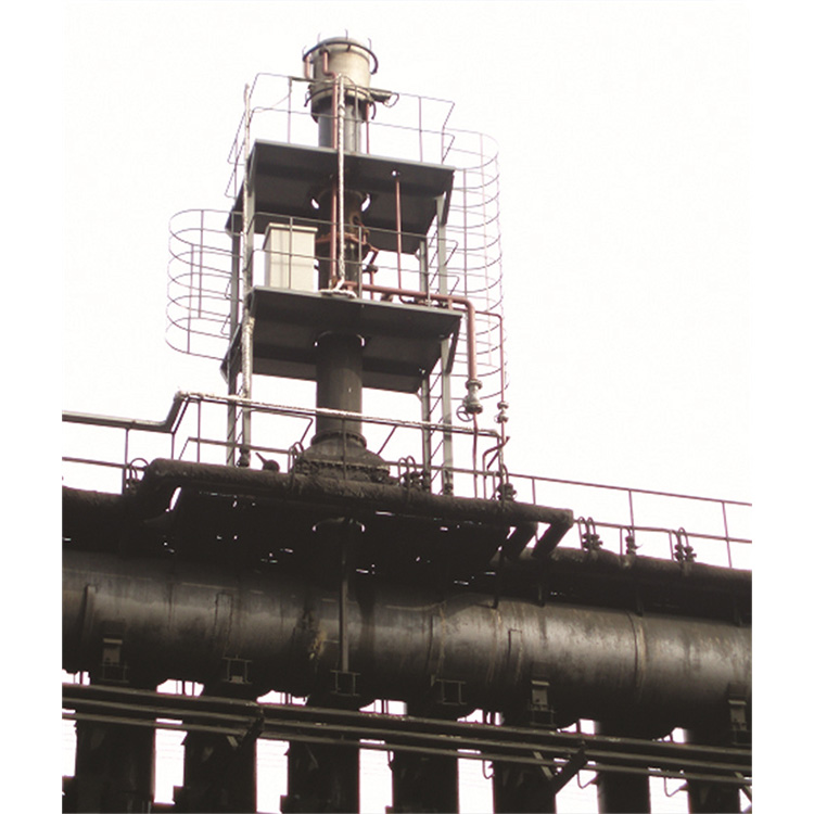
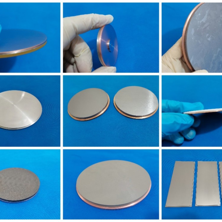
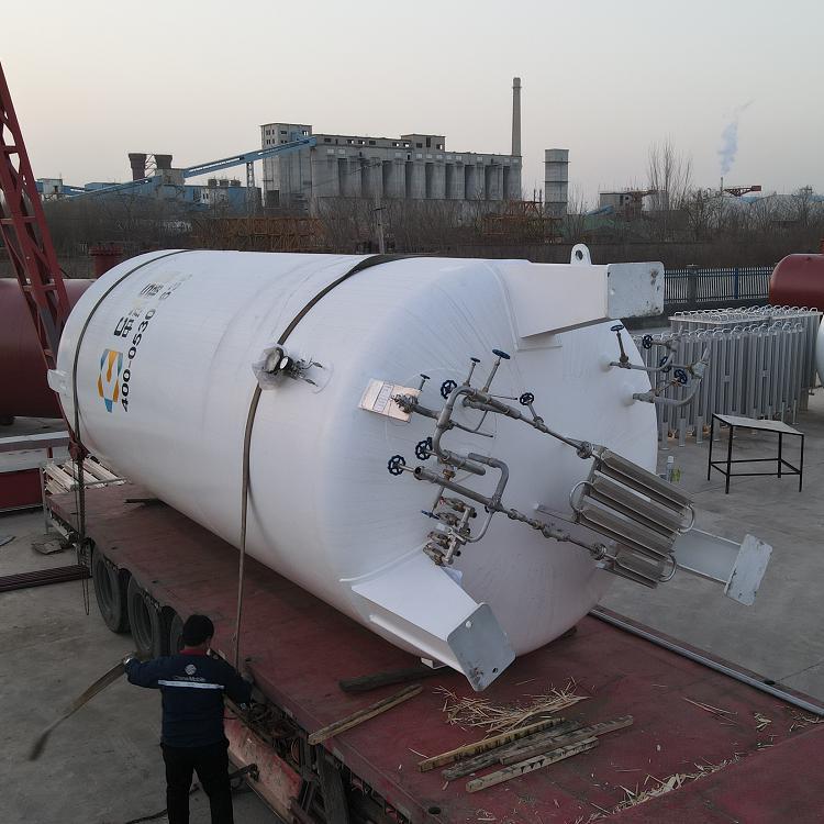
Our低温 storage tanks are one of our core business centers---the Deep Cryogenic Vessel Business Center's main products include vertical and horizontal storage tanks for low-temperature liquids ranging from 5 to 200 cubic meters, such as Liquefied Natural Gas (LNFG), Liquid Oxygen (LO2), Liquid Nitrogen (LN2), Liquid Argon (LAr2), and Carbon Dioxide (LCO2) tanks.
Low-temperature storage tanks are pressure vessels used to store low-temperature liquefied natural gas, liquid oxygen, liquid nitrogen, liquid argon, liquid carbon dioxide, and other media. These storage tanks are double-walled fixed vacuum powder-insulated (storage containers). The inner shells for liquefied natural gas, liquid oxygen, liquid nitrogen, and liquid argon are made of stainless steel, while the carbon dioxide storage tank is made of 16MnDR. The outer shell material is Q345R or 16MnR. The surface anti-corrosion coating is applied using sandblasting, sweeping, and spraying techniques, and also features imported Jotun coatings from Norway to ensure the paint does not peel off for 5 years.
Product Details Image
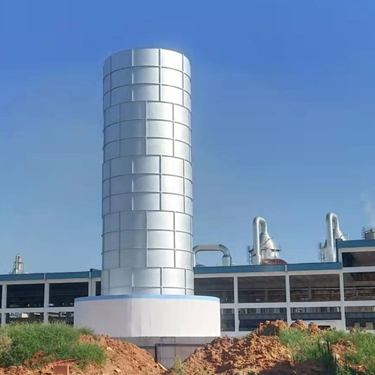
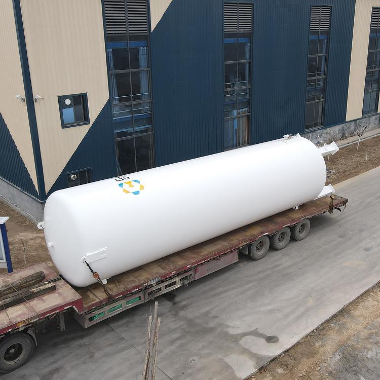
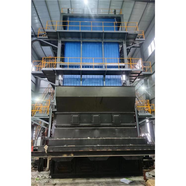
Low-temperature storage tanks use pearlite sand as insulation material in the interlayer between the inner and outer containers, evacuated and heated to achieve insulation effects.
Low-temperature storage tanks are primarily used for the cryogenic storage of gases such as liquefied natural gas, liquid oxygen, liquid nitrogen, liquid argon, and carbon dioxide. One cubic meter of liquid can replace 130 gas cylinders. It can substitute for the daily transportation of gas cylinders, saving a significant amount of labor and materials.
Product Details Image
Variable 3 [Variable 1]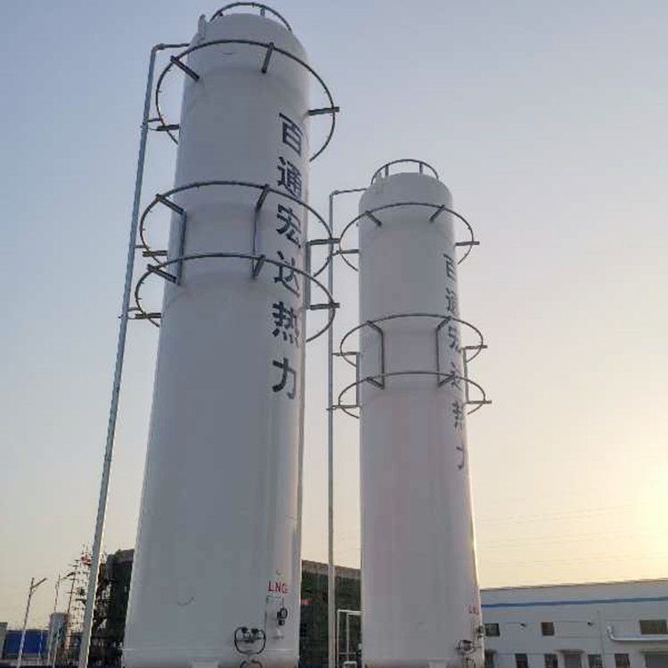
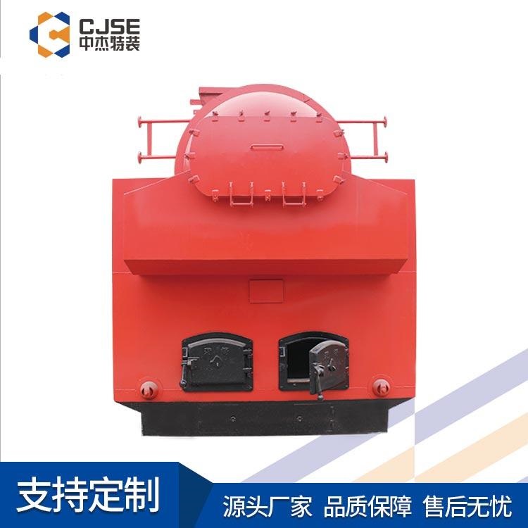
Technical Specifications
Product Details Image
Tank Type: Type II
Medium: Liquid Carbon Dioxide
Design Pressure: 2.2 MPa
Maximum Working Pressure: 2.27 MPa
Volume: 10.5 m³
Materials:
Liner: 16MnDR
Exterior Shell: Q345R
Specifications:
Liner: φ16008/8
Exterior Case: φ21008/8
Total Weight: 7,600 kg
Sandwich insulation material:
CEP60 Pearl Sand (Moisture Content ≤0.3%)
Liner Pressure Test
Medium: Nitrogen Test Pressure: 2.61 MPa
Liner Tube Materials: S30408
Valve: Cryogenic Stainless Steel Three-Stage Ball Valve
Manufacturing Acceptance Standards:
According to GB/T 18442-2011 Stationary vacuum insulated cryogenic pressure vessel
TSG 21-2016 Safety technical supervision procedures for fixed pressure vessels
【Product Details Image】
Variable 3 | Variable 2 | Variable 1
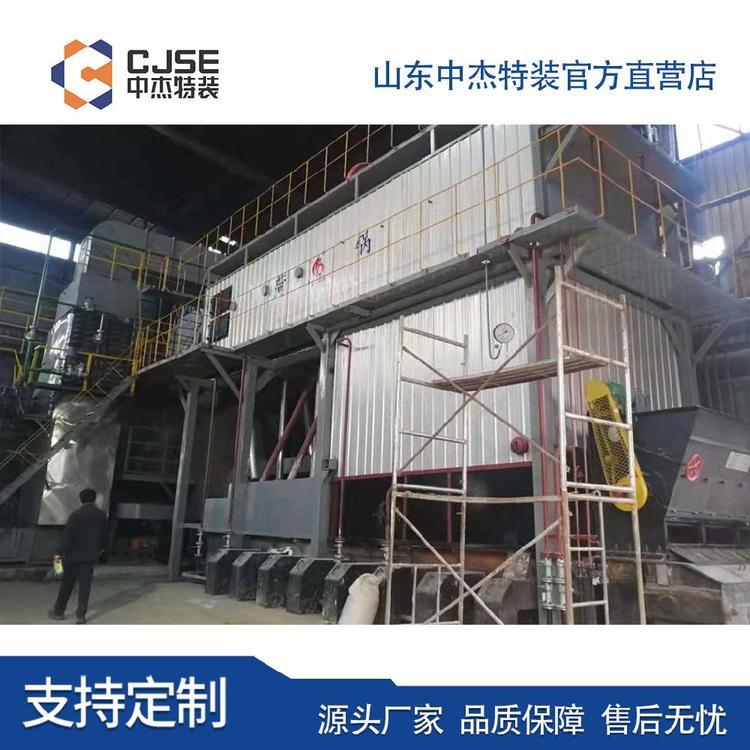
Tank pressurization
[Product Details Image]
When the tank is supplying liquid outward and requires a stable discharge pressure, a vaporizer (supplied separately) can be used for pressurization. The operation process is as follows:
The carburetor (available separately) can be used for boosting when the reservoir is supplied externally and requires stable discharge pressure. The operation is as follows:
2.3.1 Open the V2 drain valve to vaporize the liquid carbon dioxide in the vaporizer. Then, open the V3 return valve (depending on the user's return gas pipeline setup, the V3 return valve can be kept in a permanent open state) to allow the gas分流 from the vaporizer to return to the upper part of the storage tank, increasing the pressure inside the tank.
Open the V2 drain valve to vaporize the liquid carbon dioxide vaporizer and open the V3 return valve (the V3 return valve can be normally open depending on the return air line of the user). The gas diverted from the vaporizer returns to the upper part of the tank , So that the pressure tank.
2.3.2 When the pressure inside the storage tank reaches 2.1 Mpa, the V3 return gas valve may be temporarily closed.
When the tank pressure reaches 2.1Mpa, the valve can be temporarily closed V3 return gas valve.
2.3.3 During the draining process, the boost capacity can be maintained at a stable pressure level by controlling the opening of the V3 return gas valve.
During drainage, the degree of pressurization can be maintained at a pressure-stable level by controlling the opening of the V3 return valve.
Product Details Image
WeChat Official Account

Scan to follow Official Account