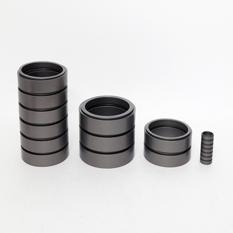


Introduction to Ring Spring
I. Scope
This document specifies the definition, classification, design calculation, technical requirements, testing methods, inspection rules, marking, packaging, transportation, and storage of annular springs.
This document applies to annular springs with outer diameters ranging from Φ18mm to Φ500mm.
Section II: Standard Reference Documents
The contents of the following documents are incorporated into this document as essential terms by normative references within the text. For referenced documents with dates, only the version corresponding to that date applies to this document; for referenced documents without dates, the latest version (including all amendments) applies to this document.
GB/T 230.1 Rockwell Hardness Test, Part 1: Test Method
GB/T 1031 Surface Roughness Parameters and Their Values
GB/T 1182 Geometrical Tolerancing - General Principles - Definitions, Symbols, and Representation of Drawing
GB/T 1184-1996 Geometrical Tolerances - Tolerances Not Specified
GB/T 1222 Spring Steel
GB/T 1800.1 Limits and Fits Basic Part 1: Vocabulary
GB/T 1800.2 Tolerance and Fit - Basic Principles - Part 2: Basic Rules for Tolerances, Deviations, and Fits
GB/T 1800.3 Limits and Fits Basic Part 3: Tables of Standard Tolerances and Basic Deviations
GB/T 1800.4 Limits and Fits Basic Part 4: Standard Tolerance Grades and Limits of Fit Tables for Holes and Shafts
GB/T 1804-2000 General Tolerance; Tolerance of Linear and Angular Dimensions Not Specified
GB/T 1805 Spring Terminology
GJB 2028 Magnetic Particle Inspection
III. Terms and Definitions
Terms and definitions as defined in GB/T 1805 and the following apply to this document.
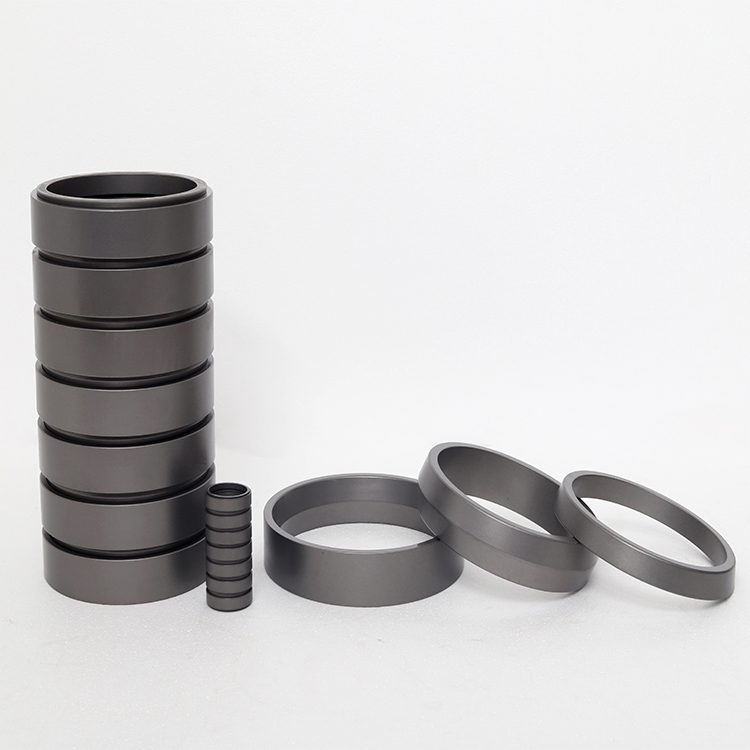
3.1 Inner Ring
Inner ring with external working cone surfaces on both ends
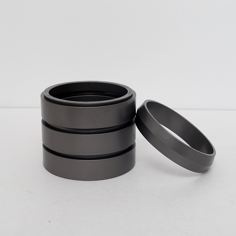
3.2 External (Outer) Ring
Outer ring with internal working cone surfaces on both ends.
3.3 End Ring
An inner ring with only one end featuring an external working cone surface, situated at the ends of a circular spring.
IV. Parameter Names, Symbols, and Units
Table 1's parameter names, symbols, and units apply to this document. For convenience, a structural illustration is provided as shown in Figure 1.
Table 1: Parameter Name, Symbol, and Unit
Serial Number | Parameter Name | Symbol | Unit | Description |
1 | Spring Inner Diameter | D1 | mm | |
2 | Spring Outer Diameter | D2 | mm | |
3 | Inner diameter | D1' | mm | |
4 | Outer diameter inside the outer ring | D2' | mm | |
5 | Initial Working Load | P1 | N | |
6 | Work completed load | P2 | N | |
7 | Spring Free Length | H0 | mm | |
8 | Starting Work Height | H1 | mm | |
9 | End of Shift Height | H2 | mm | |
10 | Ring thickness | h | mm | |
11 | Spacing after spring loading | S | mm | |
12 | Conical Half-Angle | β | ° | |
13 | Inner ring small cone diameter | d1 | mm | |
14 | Outer ring large cone diameter | d2 | mm | |
15 | Deformation amount | f | mm | |
16 | Load | F | N |
V. Technical Requirements
5.1 Dimensions
5.1.1 The inner diameter, outer diameter, free height, and compressed height of the annular spring should comply with the specifications in the product drawing.
5.1.2 The inner and outer ring dimensions of the annular spring should conform to the relevant provisions of GB/T 1800.1~GB/T 1800.4, and the allowable deviations of unnoted tolerance dimensions should comply with the m-class regulations in GB/T 1804-2000.
5.1.3 The inner and outer rings of the annular spring should conform to the shape and position tolerances specified in GB/T 1182, GB/T 1184~1996, or as indicated in the product drawings. If the shape and position tolerances are not specified, they should comply with the k-grade requirements of GB/T 1184-1996.
5.1.4 The radial dimensions and tolerances of the inner and outer rings of the annular spring shall comply with the specifications in Table 2, and the shape of the inner and outer rings is as shown in Figure 2.
Table 2: Radial Dimensions and Deviations
Outer Diameter Size | Inner ring | Outer Ring | ||
D1 | D1' | D2 | D2' | |
ϕ18~ 500 | H9/H10 | h8/h9 | H8/H9 | h9/h10 |
Table 3: Other Sizes and Deviations
Diameter | Project | |||
H0 | h | δ | β | |
ϕ18~30 | -0.2 +0.2 | -0.1 +0.1 | -0.1 +0.1 | -0.1° +0.1° |
ϕ30~50 | -0.3 +0.3 | -0.1 +0.1 | -0.1 +0.1 | -0.1° +0.1° |
ϕ50~80 | -0.4 +0.4 | -0.2 +0.2 | -0.2 +0.2 | -0.1° +0.1° |
ϕ80~120 | -0.6 +0.6 | -0.2 +0.2 | -0.2 +0.2 | -0.1° +0.1° |
ϕ120~00 | -0.8 +0.8 | -0.2 +0.2 | -0.2 +0.2 | -0.1° +0.1° |
ϕ200~300 | -1.2 +1.2 | -0.3 +0.3 | -0.3 +0.3 | -0.1° +0.1° |
ϕ300~500 | -1.5 +1.5 | -0.3 +0.3 | -0.3 +0.3 | -0.1° +0.1° |
5.2 Materials
The inner and outer rings of the circular spring should be made of materials conforming to GB/T 1222 and relevant technical agreements, and should be accompanied by a quality certificate of conformity. The materials can only be put into use after being re-inspected and approved by the contracting party. The surface of the materials should be smooth with no obvious pull marks, dents, or other defects. When other materials are required, the decision shall be made by both the supplier and the buyer.
5.3 Process
High-volume produced circular springs, with the inner and outer rings made from forged blanks, then rolled into finished shape and size on a transfer die roller, followed by heat treatment after inspection.
Ring springs produced in small quantities, with blanks forged freely and then machined to achieve the finished shape and dimensions, followed by heat treatment. Contact surfaces are ground if necessary after heat treatment.
The inner and outer rings of the annular spring should meet the surface roughness requirements of GB/T 1031 or the specifications in the product drawing. The surface roughness of the conical surfaces of the inner and outer rings is generally Ra0.4~Ra0.8.
Due to the thin ring thickness, special attention should be paid during manufacturing to prevent the ring from warping.
5.4 Appearance Quality
The inner and outer rings of the annular spring should have smooth arcs, cylindrical surfaces, and end faces, without any damage, warping, burrs, or fractures.
5.5 Internal Quality
The inner and outer rings of the annular spring should not have cracks and blow holes, or other internal defects.
5.6 Design and Structure
5.6.1 The design of the circular spring should consider the requirements for stiffness, strength, and motion stability. It should meet the smoothness of movement for the entire caching system and adapt to its working environment.
5.6.2 The structure of the annular spring should meet the basic requirements that there is no sticking phenomenon between the inner and outer rings under lubrication conditions.
5.6.3 The annular spring should be guided by the inner guide rod, with the gap between the annular spring and guide rod not exceeding D1 × 2% on one side; for guidance by the outer guide tube, the gap between the annular spring and guide tube should not exceed D2 × 2% on one side.
5.6.4 The typical design characteristic curve OABO of a circular spring within a loading and unloading cycle should be as shown in Figure 3. The OA section indicates that the compression of the circular spring during loading is proportional to the load; the AB section indicates that during the initial unloading phase, the compression should remain essentially unchanged and exhibit a significant hysteresis characteristic; the BO section indicates that as the load decreases to a certain extent, the compression begins to decrease and continues to decrease to zero during the unloading process, at which point the circular spring starts to extend and should return to its original size.
5.6.5 The annular spring should possess well-designed vibration-damping properties, with the total energy loss upon deformation and subsequent recovery generally not less than 50%.
5.6.6 Inner and Outer Ring Hardness
The inner and outer rings of the annular spring should generally have a surface hardness value of 48HRC-54HRC after heat treatment.
5.6.7 Surface Treatment
The inner and outer rings of the annular spring should be subjected to anti-rust treatment in accordance with relevant standards after mechanical processing, such as phosphatizing and oxidizing.
5.6.8 High Pressure Treatment
Circular springs should be subjected to a high-pressure treatment; unless otherwise specified, the general high-pressure treatment duration should not be less than 24 hours.
5.6.9 Run-in Treatment
Circular springs should be磨合 according to the product drawing specifications. If the drawing does not specify the number of磨合 cycles, the general number of磨合 cycles should not be less than 10.
5.6.10 Workload
The circular spring, after being subjected to high-pressure and磨合 treatment, should meet the specified working load (P1 or P2) as indicated in the product drawing or contract.
5.6.11 Adhesion Rate
The fit rate between the inner and outer rings of the annular spring and the conical contact surfaces should not be less than 75%.
5.6.12 Life span
The service life of the circular spring should comply with the specifications of the product drawings and the technical requirements for manufacturing acceptance.
Six, Inspection Rules
6.1 Inspection Conditions
Subject to specific provisions, the following conditions shall apply:
a) Indoor Inspection: Temperature 5℃ ~ 35℃, relative humidity not exceeding 80%.
Outdoor Inspection: When using instruments, they should comply with the environmental requirements permitted by the instruments.
6.2 First Article Inspection
6.2.1 The initial identification inspection items for annular springs should be in accordance with the product drawings, contract, and the provisions of Table 4.
6.2.2 The inspected samples for the first piece inspection should not be fewer than two.
6.2.3 When all inspected samples and all items of the initial inspection meet the requirements of this specification, the initial inspection is deemed to pass; if any inspected sample or any inspection item of the initial inspection does not meet the requirements of this specification, the initial inspection is deemed to fail.
Table 4: Inspection Items List
Serial Number | Inspection Items | Requirements Article Number | Inspection Method Article Number | First Article Inspection | Quality Consistency Inspection | ||
A | B | C | |||||
1 | Dimensions | 5.1 | 6.4.1 | ● | ● | - | - |
2 | Appearance quality, surface treatment | 5.2、5.5.7 | 6.4.2 | ● | ● | - | - |
3 | Internal Quality | 5.3 | 6.4.3 | ● | ● | - | - |
4 | Interior and exterior ring hardness | 5.5.6 | 6.4.4 | ● | ● | - | - |
5 | High-pressure treatment | 5.5.8 | 6.4.5 | ● | ● | - | - |
6 | Lubrication and磨合处理 | 5.5.9 | 6.4.6 | ● | ● | - | - |
7 | Workload | 5.5.10 | 6.4.7 | ● | ● | - | - |
8 | Adhesion rate | 5.5.11 | 6.4.8 | ● | - | ○ | - |
9 | Service Life | 5.5.12 | 6.4.9 | ○ | - | - | ○ |
Note: ● Mandatory Inspection Items; ○ Inspection Items as Per Product Drawing or Contract; - Non-Inspection Items | |||||||
6.3 Quality Consistency Inspection
6.3.1 Sampling Plans, Grouping Rules
Circular springs for batch inspection shall consist of inner and outer rings made from the same specification and brand of steel, produced under the same process conditions. The batch size for inspection shall be as specified by the product drawing or contract.
Group A inspection items follow a full inspection plan, while Group B and C inspection items are executed according to the sampling plan specified in the product drawings or contract.
6.3.2 Qualification Criteria
If all items in Group A inspection meet the requirements of this specification, Group A inspection is deemed to pass; if any inspection item in Group A does not meet the requirements of this specification, Group A inspection is deemed to fail.
Products deemed不合格 in Group A inspection can be re-inspected after repair;不合格 items should be removed.
If a single ring part breaks during the high-pressure treatment inspection and the number does not exceed 3% of the inspected batch, it may be replaced with a high-pressure treated inner or outer ring and re-inspected. If the number of broken single ring parts exceeds the above specification, the batch should be re-inspected with double the time. If another single ring part breaks during the re-inspection, the batch is deemed不合格 for Group A inspection.
If any sample from Group B inspection fails to meet the specifications, double the number should be retested. If another sample still fails to meet the specifications, the batch will be deemed不合格 for Group B inspection.
B-group inspection failed batches can be subject to full inspection and non-conforming items can be removed.
If one sample from the C group inspection does not meet the requirements of this specification, double the number of samples should be re-inspected. If another sample still fails to meet the requirements, the batch will be deemed不合格 for the C group inspection.
6.4 Inspection Methods
6.4.1 Dimensions
Inspection using general or interchangeable measuring tools that have been calibrated; the measuring tools for inspecting the inner or outer diameter must have a least count of not less than 0.05mm.
6.4.2 Appearance Quality, Surface Treatment
Inspect the appearance quality and surface treatment by visual inspection, tactile feel, or reference to standard samples. In case of disputes, a 5x magnifying glass can be used for examination.
6.4.3 Internal Quality
Inspect in accordance with the requirements of GJB 2028.
6.4.4 Inner and Outer Ring Hardness
Inspected in accordance with GB/T 230.1 specifications.
6.4.5 High Pressure Treatment
The annular spring is subjected to high-pressure treatment on a pressure testing machine, compressing it until the coils touch without significant gaps, or until the specified height for the product is reached, or until the specified load for the product is applied, and then maintaining the specified duration of action. After the high-pressure treatment, the appearance quality is inspected visually.
6.4.6 Break-in treatment
The磨合processing is conducted after the strong pressure processing passes the qualification.
The annular spring should be kept under pressure on the磨合试验机, and operated to travel between H1 and H2 as specified in Section 3.9.2. The entire process should not be interrupted and should be completed in one continuous operation.
6.4.7 Workload
The determination of work load should be conducted after the磨合 treatment has been qualified.
On the pressure testing machine, compress the annular spring to H1 or H2, and measure and record the working load P1 or P2.
When the work load does not comply with the product drawing or contract specifications, adjustable washers can be used for adjustment. The thickness and quantity of the washers should conform to the requirements of the product technical specifications.
6.4.8 Tensile Fit
The test is conducted using the coal tar method.
6.4.9 Life Span
Conduct fatigue tests on the circular springs, ensuring the stroke corresponds to the actual working stroke, the reciprocating frequency matches the working frequency, and the running times should not be less than 110% to 130% of the actual working life. After the fatigue test, inspect or check the working load, internal quality, and appearance quality of the circular spring to ensure they meet the requirements of the corresponding product drawings and this specification, and record the findings.
7. Branding, Packaging, Transportation, and Storage
7.1 Brand
7.1.1 A clear durability mark should be present in a prominent location on the circular spring.
7.1.2 The logo should include the following:
Product Model
b) Product Trademark;
c) Manufacturer's name or code;
d) Manufacturing Date (Year, Month).
7.1.3 Products that pass the factory inspection should have a certificate of conformity or a conformity mark.
7.1.4 Certificate of Compliance includes: (1) Product name, model, specifications; (2) Product number; (3) Manufacturer's name or code; (4) Manufacturing year, month; (5) Inspector.
7.2 Packaging
7.2.1 The product's packaging and storage labels should meet the customer's requirements.
7.2.2 The packaging should ensure that it is not subject to compression and deformation.
7.2.3 The packaging box surface should have product name, quantity, and protective markings.
7.2.4 The packaging box should indicate the stacking direction and the number of layers allowed for stacking.
7.2.5 The packaging box should include a product certification and a product manual.
7.3 Transportation and Storage
7.3.1 The packaging box of the circular spring should be kept upright during transportation and storage, and should not be laid horizontally, nor should there be any damage to the packaging.
7.3.2 Ring springs should be handled to avoid impact during transportation and storage. They should be kept away from acids, alkalis, salts, oils, water, soot, and other organic solvents, and should be as far away from heat sources as possible.
A.1 Common Ring Spring Size Series is shown in Table A.1
Table A.1
D2 | D1 | h | t | δ0 | β | F | Gea |
mm | mm | mm | mm | mm | ° | kN | kg |
18.1 | 14.4 | 3.6 | 4.4 | 0.8 | 13.1 | 5 | 0.002 |
25 | 20.8 | 5 | 6.2 | 1.2 | 13.5 | 9 | 0.004 |
32 | 27 | 6.4 | 8 | 1.6 | 13.4 | 14 | 0.007 |
38 | 31.7 | 6.4 | 9.4 | 1.8 | 13.4 | 20 | 0.012 |
42.2 | 34.6 | 8.4 | 10.4 | 2 | 13.2 | 26 | 0.018 |
48.2 | 39.4 | 9.6 | 11.8 | 2.2 | 13.4 | 34 | 0.026 |
55 | 46 | 11 | 13.6 | 2.6 | 13.2 | 40 | 0.035 |
63 | 51.9 | 12.6 | 15.4 | 2.8 | 13.3 | 54 | 0.056 |
70 | 58.2 | 14 | 17.2 | 3.2 | 13.2 | 65 | 0.074 |
80 | 67 | 16 | 19.6 | 3.6 | 13.5 | 83 | 0.105 |
90 | 75.5 | 18 | 22 | 4 | 13.3 | 100 | 0.145 |
100 | 84 | 20 | 24.4 | 4.4 | 13.5 | 125 | 0.203 |
130 | 111.5 | 24.8 | 30 | 5.2 | 13.4 | 160 | 0.376 |
124 | 102 | 24.8 | 30 | 5.2 | 13.3 | 200 | 0.408 |
140 | 116 | 28 | 34 | 6 | 13.3 | 250 | 0.568 |
300 | 250 | 60 | 77 | 11.6 | 13.2 | 1000 | 5.51 |
320 | 263 | 64 | 76.4 | 12.4 | 13.1 | 1200 | 7.06 |
350 | 288 | 70 | 83.2 | 13.2 | 13.2 | 1400 | 9.18 |
400 | 330 | 80 | 95.2 | 15.2 | 13.1 | 1800 | 13.56 |
Weight of the corresponding annular spring for a pair of contact surfaces | |||||||
B.1 Selection of Ring Spring Design Parameters
(1) Cone Surface Angle: When the cone surface angle β is chosen to be smaller, the spring stiffness is reduced. If β < ρ, self-locking will occur during unloading, meaning it cannot rebound. If β is chosen too large, the load PR during elastic deformation recovery will be greater, reducing the shock-absorbing capacity of the annular spring. During design, β can be selected between 12° to 20°. When the cone surface processing precision is high, β can be 12°; when the processing precision is average, β is often 14.04°; and when lubrication conditions are poor and the friction coefficient is high, β should be larger to avoid self-locking.
(2) The coefficient of friction fμ and the friction angle ρ can be selected according to the following conditions:
Raw surface under heavy-duty working conditions | ρ ≈9° | fμ ≈ 0.16 |
Precision-machined surface contact under heavy-duty working conditions | ρ ≈ 8.5° | fμ ≈ 0.15 |
Precision-machined surface under heavy-duty working conditions | ρ ≈ 7° | fμ ≈ 0.12 |
(3) Allowable stress for annular springs is as shown in Table B.1.
Table B.1 Allowable Stress of Common Materials for Ring Springs / MPa
Processing and Usage Conditions | Permitted stress σ1p in outer ring | Permitted stress σ2p within inner ring |
For general lifespan requirements | 900 | 1200 |
For short life requirements (unprocessed surface) | 1000 | 1300 |
For short lifespan requirements (finish processed surfaces) | 1200 | 1500 |