


Tube-in-tube condenser
Tube-in-tube condenser structure
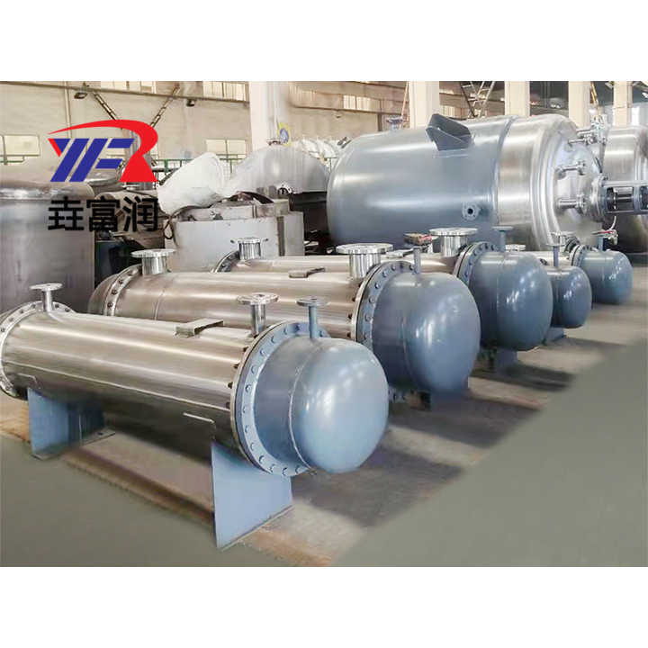
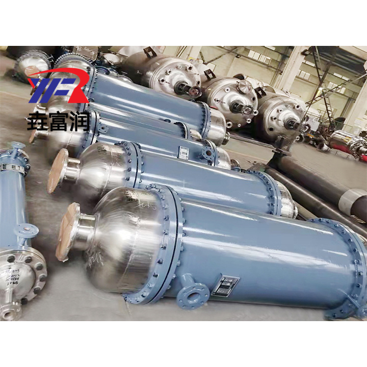
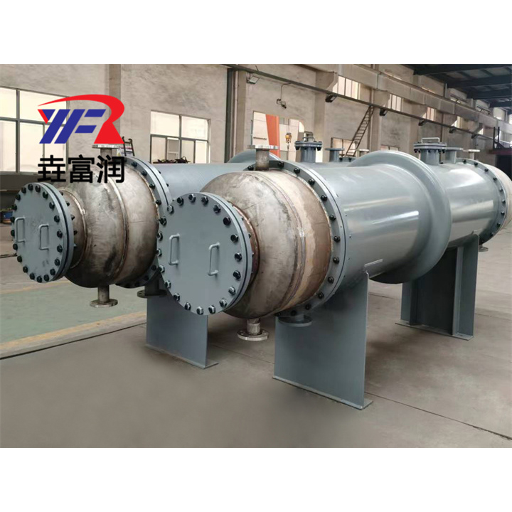
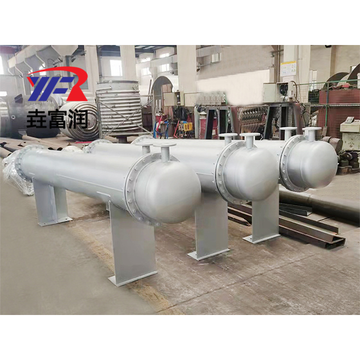
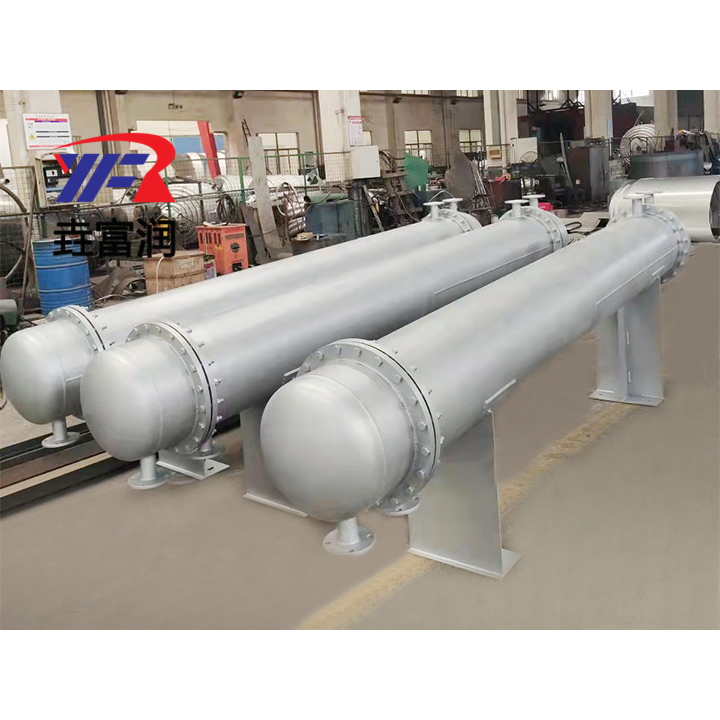
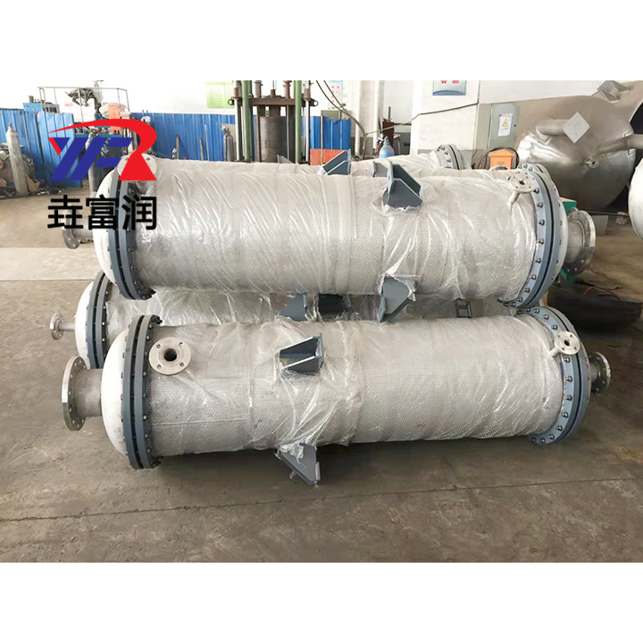
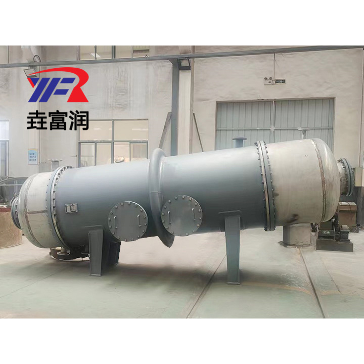
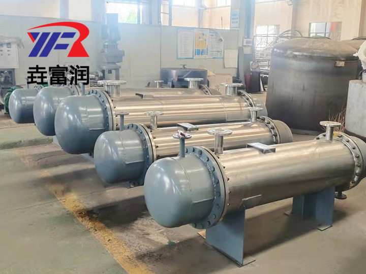
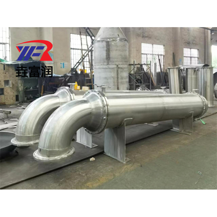
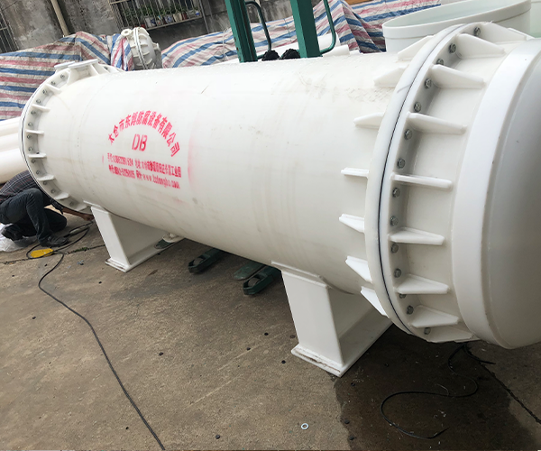
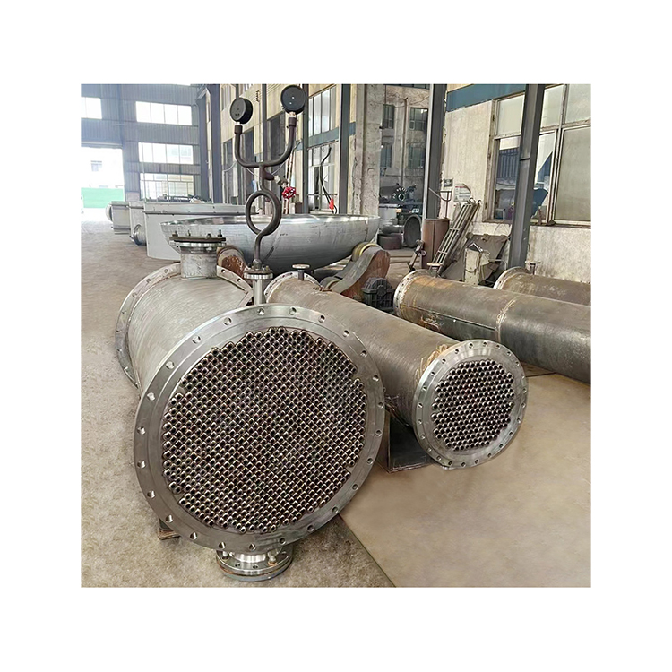
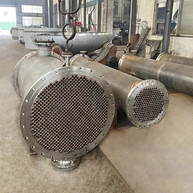
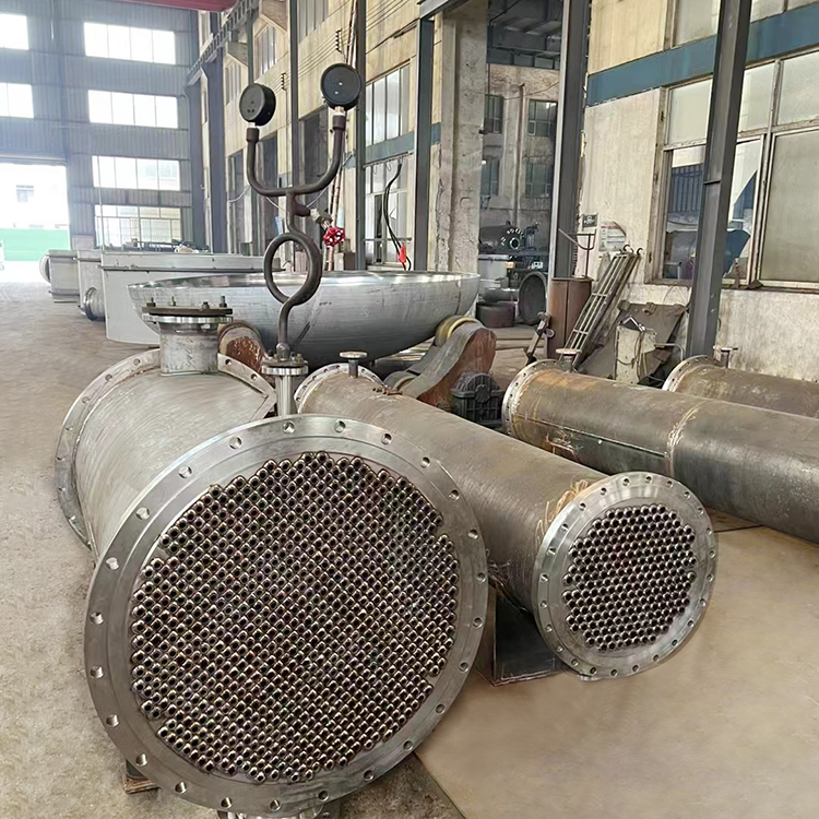
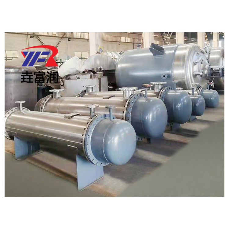
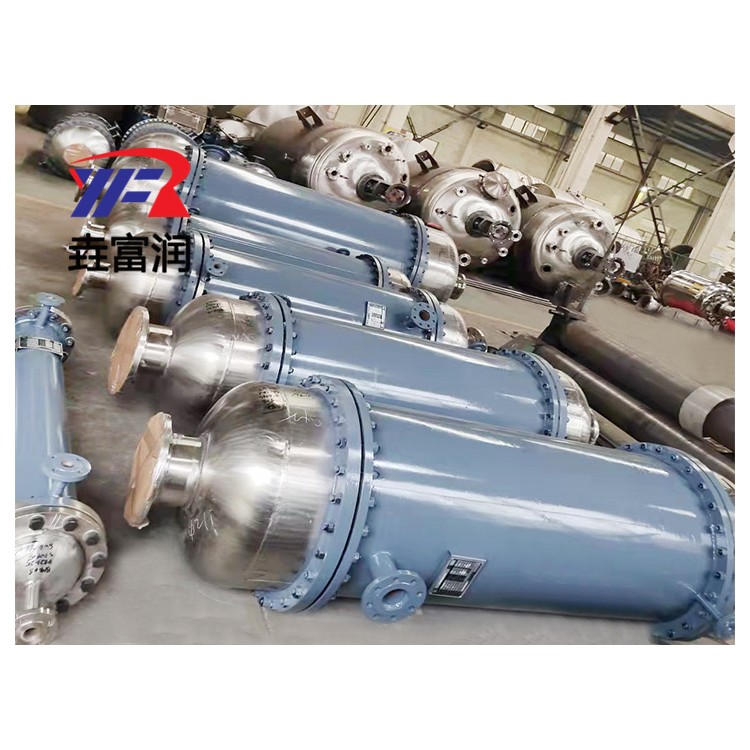
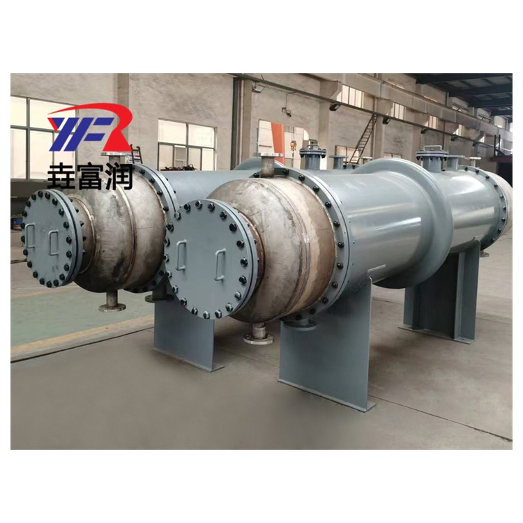
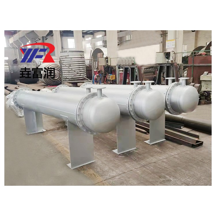
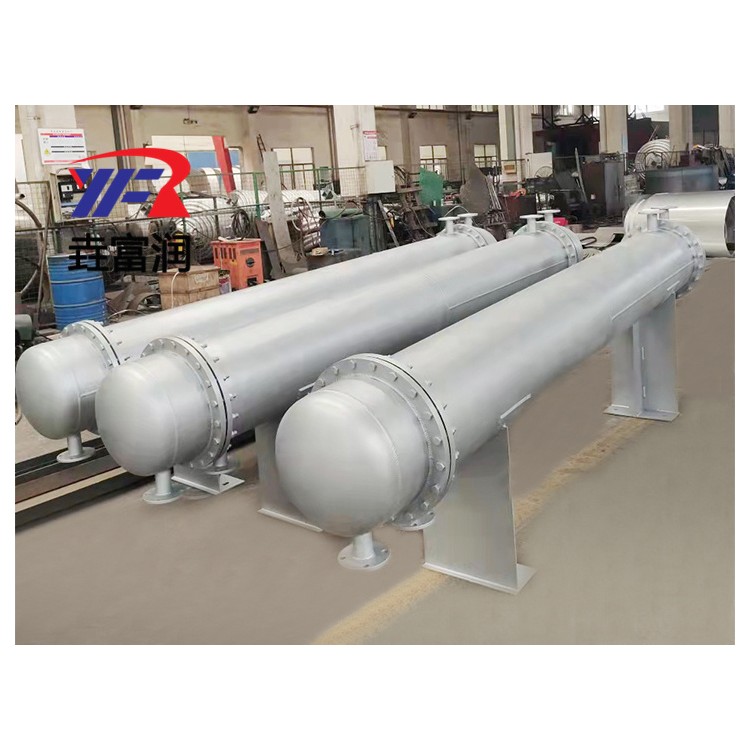
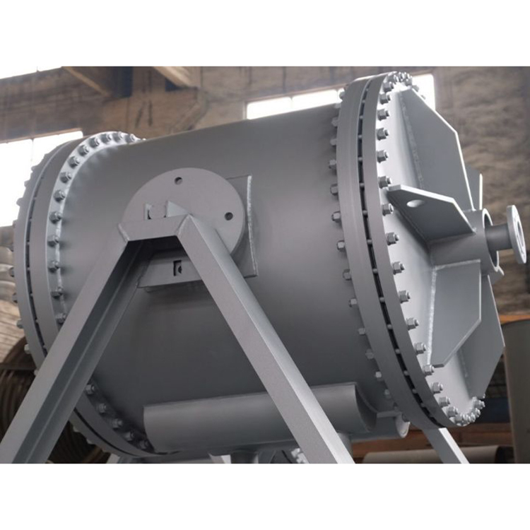
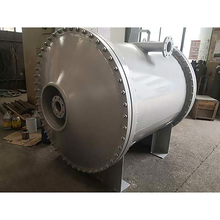
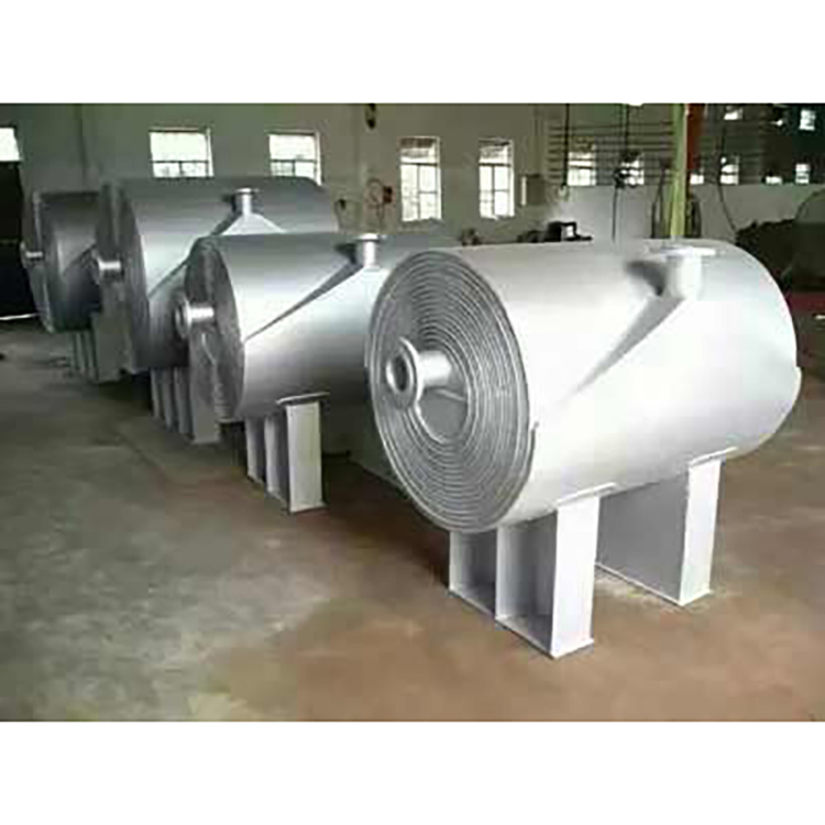
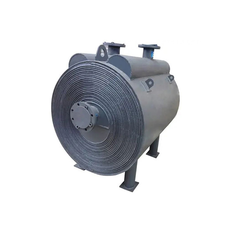
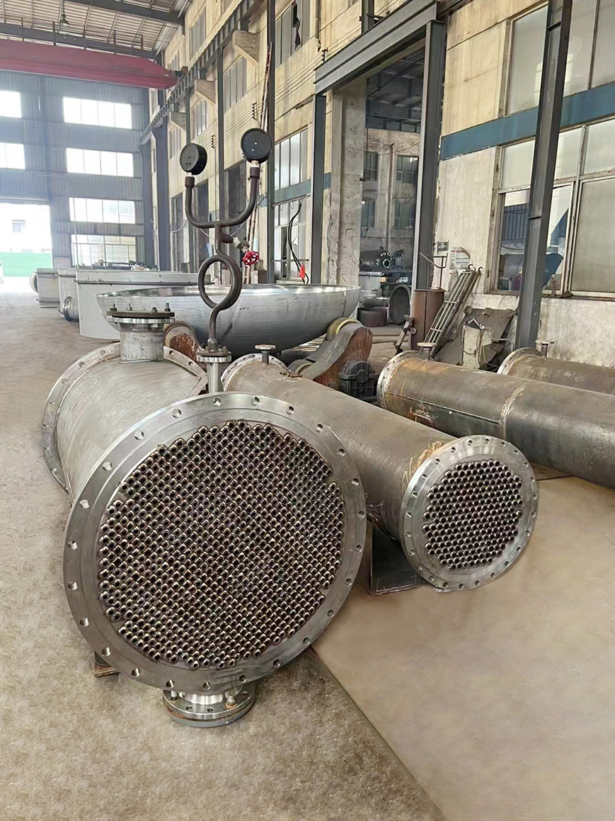
The tube-type condenser is mainly composed of the outer shell, tube plate (also known as the header), tube bundle, and top cover (also known as the head). Parallel tube bundles are installed inside the circular shell, with the ends of the tubes fixed on the tube plate. The method of fixing tubes on the tube plate is generally welding or expansion. The top cover, equipped with import or export tubes, is connected to the outer shell flanges at both ends with screws, forming a fluid distribution chamber between the top cover and the tube plate. It is widely used due to its simple and sturdy structure, ease of manufacturing, broad material range, high processing capacity, and strong adaptability.
During heat exchange, the cooling water enters through the connection pipe at the top cover, flows within the pipes, and this path is called the tube side; harmful vapor flows in the gap between the tube bundle and the shell, and this path is called the shell side; the surface area of the tube bundle is the heat transfer area. In the condensation recovery process, whether it is the condensation of saturated vapor or the condensation with non-condensable gas, generally speaking, the condensation in the shell side of the horizontal condenser is more reasonable, as it is more suitable in terms of heat transfer, pressure drop, and cleaning.
Tube-in-tube condenser classification
(1) Fixed tube sheet heat exchangers: Simple and compact structure, capable of withstanding high pressure, cost-effective, easy to clean in the tube side, and convenient to block or replace tubes when damaged.
(2) Floating Head Heat Exchangers: Easy to clean inside and between the tubes, and do not generate thermal stress.
(3) U-tube Heat Exchanger: Featuring a single tube sheet, the tube bundle is composed of multiple U-shaped tubes, with both ends of the tubes fixed on the same tube sheet, allowing for free expansion and contraction. No thermal stress is generated when there is a temperature difference between the shell and the U-tube heat exchanger.
(4) Sliding tube sheet heat exchangers: Simple structure, low cost, and can add baffles to the tube box as needed to enhance heat transfer.
Features of Tube-in-Tube Condensers
(1) Horizontal shell-side condensing film heat transfer coefficient is several times higher than that of vertical tube internal or external film heat transfer coefficient, and non-condensibles do not accumulate in dead corners, making them easier to discharge.
(2) Cooling water flowing through pipes is convenient for cleaning scale. Water flowing within pipes ensures a higher flow rate, which is beneficial for reducing the rate of scale formation and increasing the heat transfer coefficient of the water film.
(3) Tube-in-tube condensers position the lower tubes at the cooling water inlet, allowing condensate to accumulate at the bottom to reduce its temperature. In surface condensation systems, further cooling of the condensate is crucial. High temperatures in the condensation system can lead to significant vaporization of organic gases upon contact with air. Typically, the outlet temperature of the condensate should be 60℃ or lower. Of course, an additional cooler can be added, but this will increase costs.