


One、Overview:
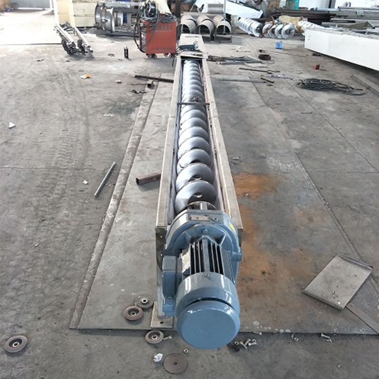
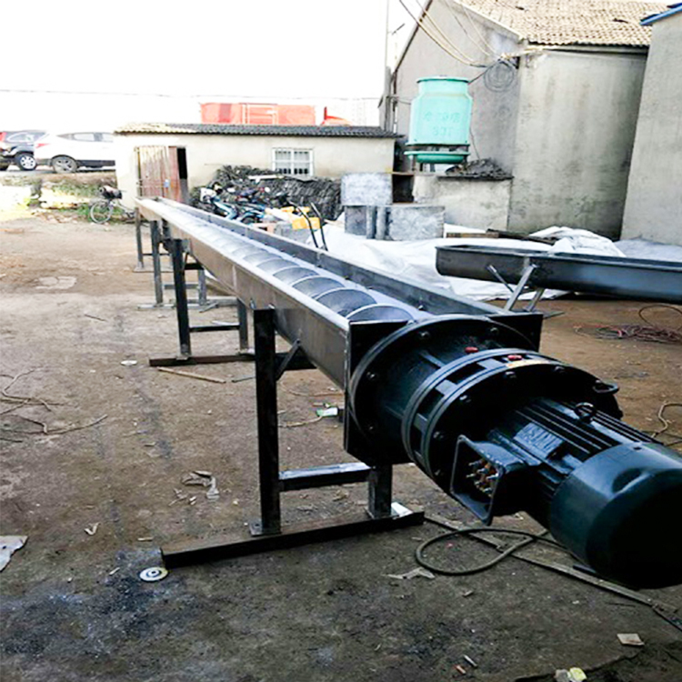
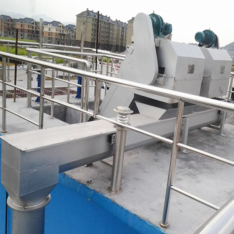
Spiral conveyors are one of the commonly used continuous conveying equipment, favored for their simple structure, small cross-sectional area dimensions, and especially for their ability to provide enclosed conveying with minimal environmental pollution. Currently, they are being used in the wastewater treatment industry as one of the material conveying devices.
II. Equipment Model Representation and Working Principle:
1. Method of equipment model notation:
![]()
![]() WLS — 300
WLS — 300
![]() Spiral Diameter (Φmm)
Spiral Diameter (Φmm)
![]() Spiral Conveyor
Spiral Conveyor
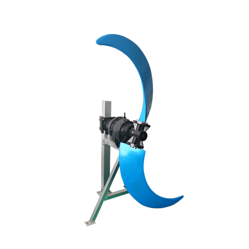
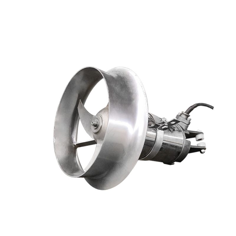
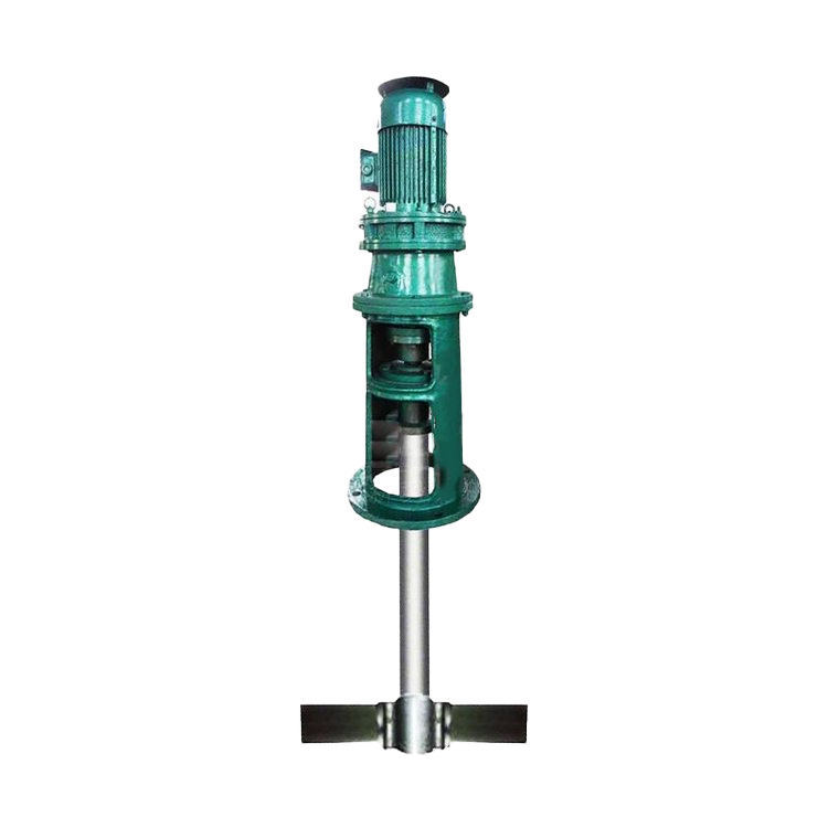
2. Working Principle:
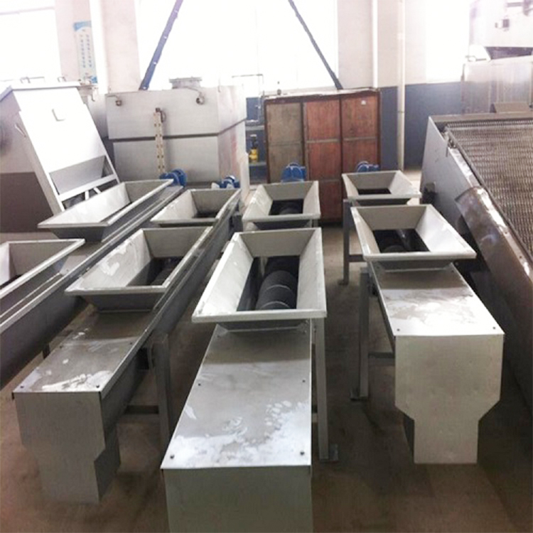
The material conveying of the screw conveyor is propelled by rotating blades sliding, with the conveying direction determining the left or right rotation of the spiral blades and their rotational direction. Thus, it can be single-direction or bi-directional conveying as needed, and multi-point loading is also possible. The conveyor can be installed horizontally or at a certain angle. Materials enter the spiral through the feeding port (5) and are conveyed or discharged through the discharge port (1) as they pass through the spiral's rotation, or they can be transported to an extruder or dehydrator for compression or dehydration before discharge. The conveyor length L is selected by the user. The power-driven unit (6) uses a double helical gear reducer or a worm gear helical bevel gear reducer. It can be mounted at the entrance (push-type spiral) or exit (pull-type spiral) end of the conveyor. The U-shaped channel at the bottom of the equipment has protective bushes that prevent wear, which are selected based on the type of conveying material.
3. Key Performance Indicators:
Spiral Diameter: Φ200 - Φ400
Speed: 12 rpm - 20 rpm
Flow Rate: Q=2-6 cubic meters/hour
Conveying Length: Less than or equal to 15 meters
Installation Inclination: ≤ 30°
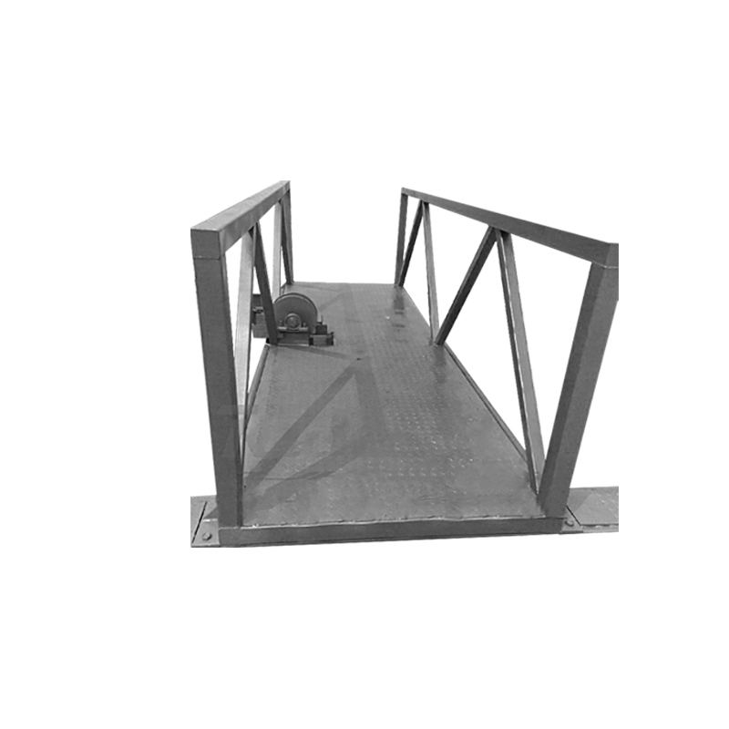
3. Installation & Commissioning:
If not specified in the order contract, the machine is factory-equipped with a ground support bracket according to the user's discharge height, and is secured during installation with expansion bolts.
2. Leave at least 0.7m of space above the top cover to ensure unhindered removal of the top cover, helix, bushes, etc., during maintenance. Whether a drain is required at the bottom of the equipment is to be selected by the customer at the time of ordering.
3. Horizontal conveyors installed horizontally have a horizontal tolerance of 1/1000 in the length direction, while those installed at an angle have an angle error of ±1 degree.
4. The equipment must not collide or slip during lifting, and effective measures must be taken to protect the stainless steel surface of the equipment, preventing any scratches, wear, and dents.
5. Check the oil level of the helical pinion reducer before starting the machine. Change the lubricating oil after 300 hours of first use. For equipment running continuously for more than 16 hours, replace the oil every 2500 hours. For equipment running 8 hours per shift, the interval can be extended to 4000 hours.
6. When conducting power-on testing, first perform a single operation to ensure there is no component friction before proceeding to normal operation.
7. Run the machine for two hours to磨合 new assembled parts, and use some appropriate lubrication (such as)
Soy sauce solution is used to reduce vibration and noise. Inspect for abnormal wear between the sleeve and the helix. Strictly prohibit rotating the helix without material and lubrication measures, as this will severely damage the sleeve. (This applies to helices without support at one end.)
Four: Usage and Maintenance
Operators must be trained and qualified before they can operate.
2. Equipment is operated in accordance with the standard inspection, maintenance, repair, and lubrication management procedures.
3. Conduct daily machine operation inspections, ensuring no abnormal noises are present. Add bearing lubricant as needed and check for any leaks in the seals. Monthly, inspect the oil level in the drive unit's gear box and adjust it to the required level.
Open the top cover every six months to inspect the wear of the spiral and sleeve, and check the tightness of all fastening connections.
Each year: Inspect sealing wear and replace as necessary.
Every two years: disassemble and overhaul the equipment, clean the bearing housing, replace worn parts, replace seals and worn bushes, inspect and align the spindles, etc.
4. The reducer speed and conveying capacity are selected according to customer requirements. The conveying material must be even and not excessive or oversized.
5. After a material blockage causes the spiral to shut down, the cause should be investigated and the fault resolved before restarting the machine.
6. When machinery is shut down for three days or more, flush or remove internal materials to prevent drying and caking (especially when temperatures are high). In winter when temperatures are low, be mindful of frost prevention. Remove any caking or freezing before restarting the machine.
V. Equipment spare parts and wear parts list:
Serial Number | Part Name | Model and Specifications | Materials | Quantity | Note |
1 | Bearings | 1 set | |||
2 | Bearings | 1 set | |||
3 | Frame Oil Seal | Rubber | 1 piece | ||
4 | Oil Cup | M10×1 | 1 piece |
Section 6: Equipment Troubleshooting
Part | Fault Condition | Fault Cause | Exclusion Measures |
Driver Equipment | Motor fails to start | Fusible link fuse blown | Identify the cause and replace the fuse |
Thermal relay trips | Identify the cause and resume | ||
Phase Loss Operation | Identify the cause and make the necessary repairs. | ||
Motor reverses direction | Incorrect wire phase sequence | Phase Shift | |
Fuses blown or thermal overload relays tripped | Electrical circuit short circuit | Repair the circuit | |
Motor short circuit | Professional repair or replacement | ||
Motor overload | Identify the cause and reduce load operation. | ||
Motor overload | Main voltage exceeds technical parameters by 5% | Guarantee the voltage value is within the motor's technical parameters range. | |
Excessive ambient temperature | Lower environmental temperature | ||
Motor fan blade is damaged | Repair and replacement | ||
Material Clog Spiral | Clear blockage | ||
Gearbox malfunction | Overhaul | ||
Gearbox failure | Internal parts wear and damage | Professionally repaired and installed | |
Safety pin break | Helical blockage | Clear material | |
Gearbox Failure | Professional repair services | ||
Screw Spinning Body | Clog | Helical Bend | Straighten or replace the helix |
Excessive materials | Remove excess material | ||
Frozen | Heating Melt | ||
Sleeve loose | Secure or replace bushes | ||
Material is extruded into the space between the hopper and the sleeve. | Exclude | ||
Sleeve loose | Loose or missing connecting screws | Secure or replace screws | |
Material adhesion and accumulation between the hopper and the spiral. | Use the correct bushing | ||
Sleeve wear | Material transport modification, does not comply with original design requirements | Adjust or replace other type bushes | |
Excessive idling time for equipment | Prevent | ||
Out Material Mouth | No shipment or Insufficient material release | Clog | Exclude |
Helical Wear | Replace the helix | ||
Excessive tilt angle during equipment installation | Minimize the tilt angle as much as possible. | ||
Insufficient materials | Adjust operating shifts and single work periods |