


I. Application, Features, Structure, and Working Process
1. Application
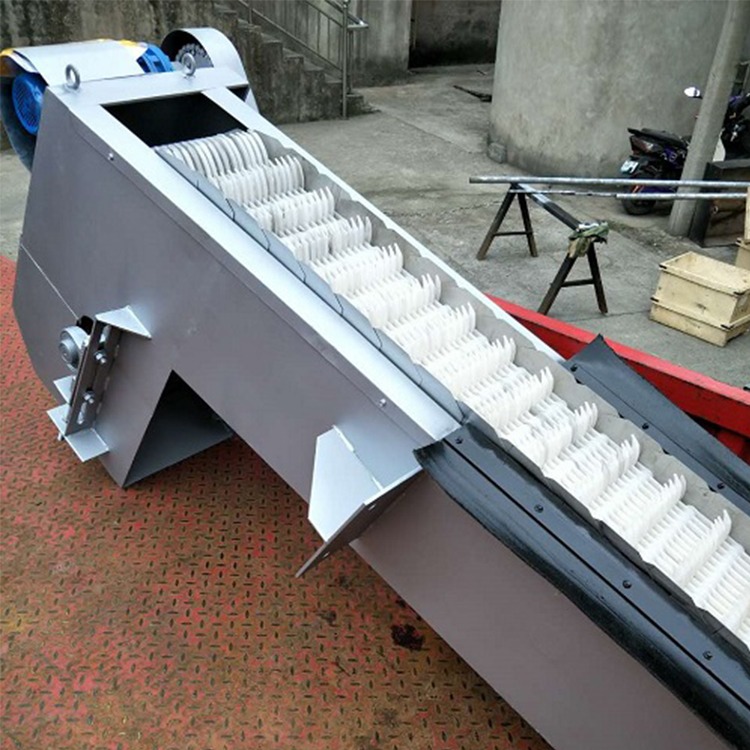
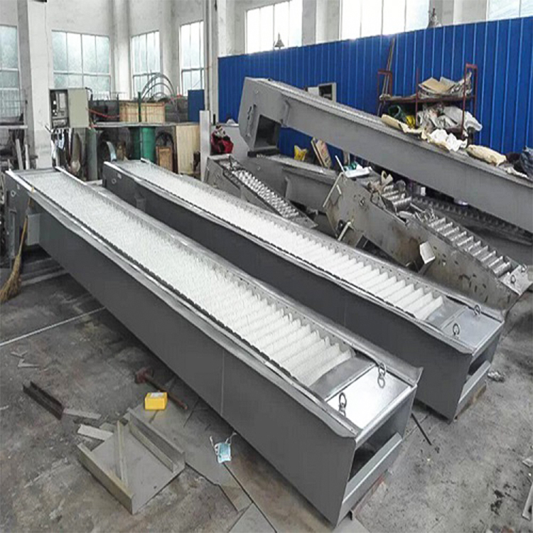
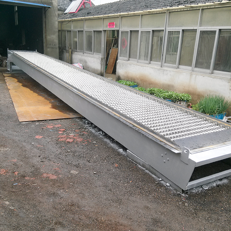
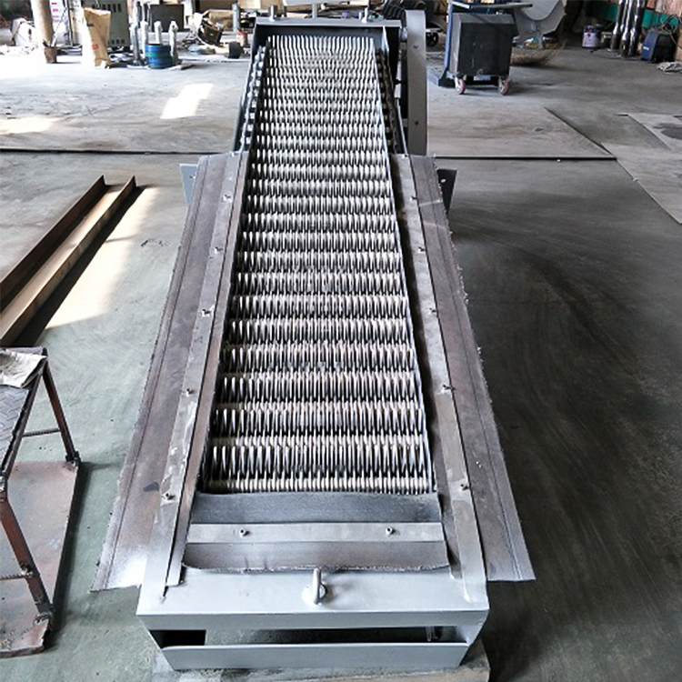
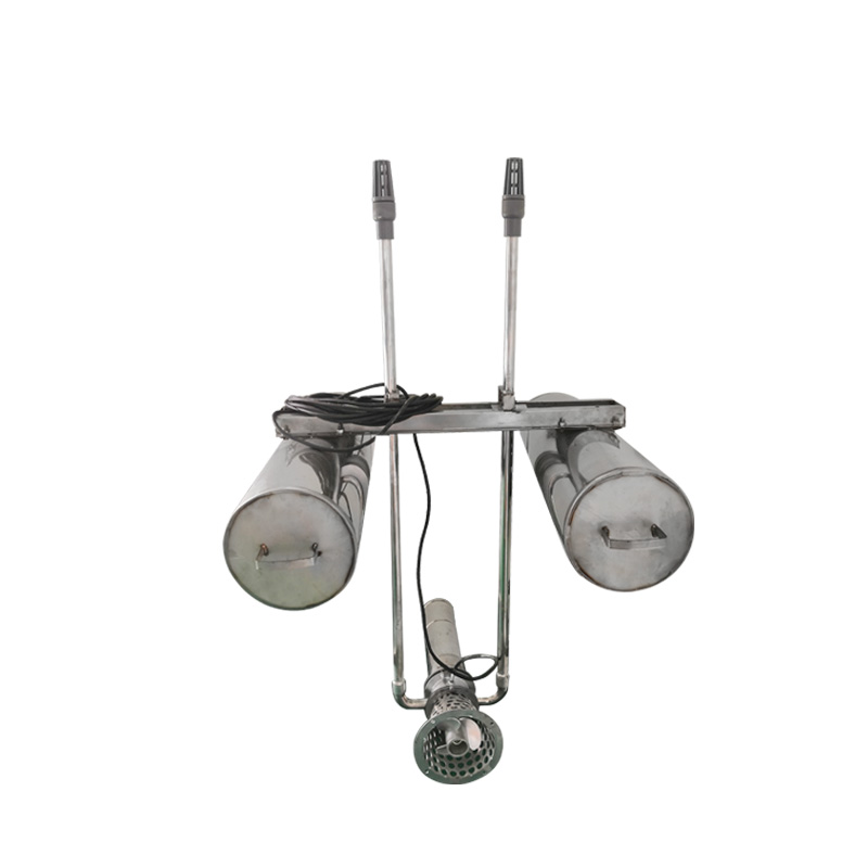
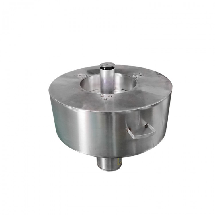
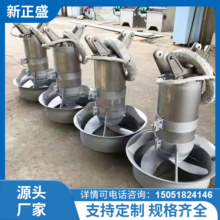
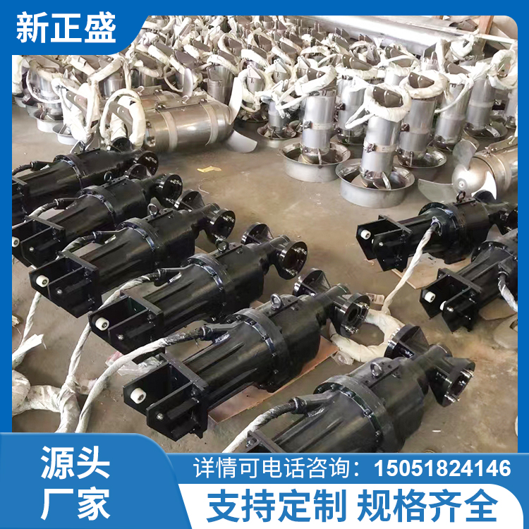
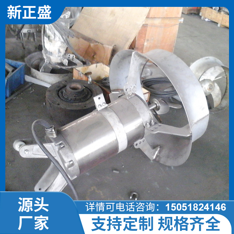
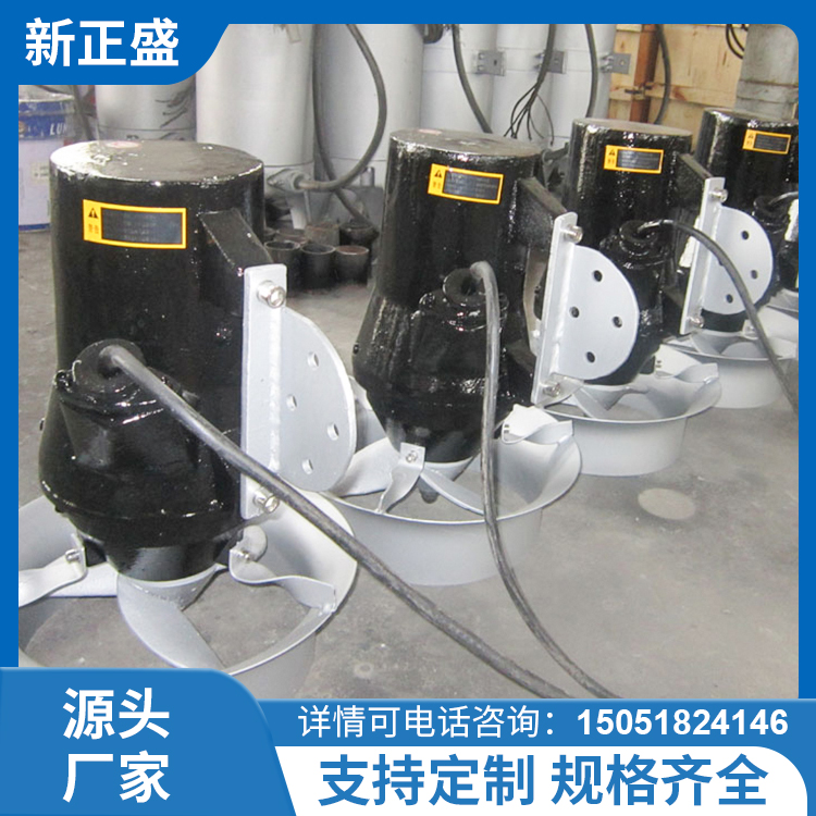
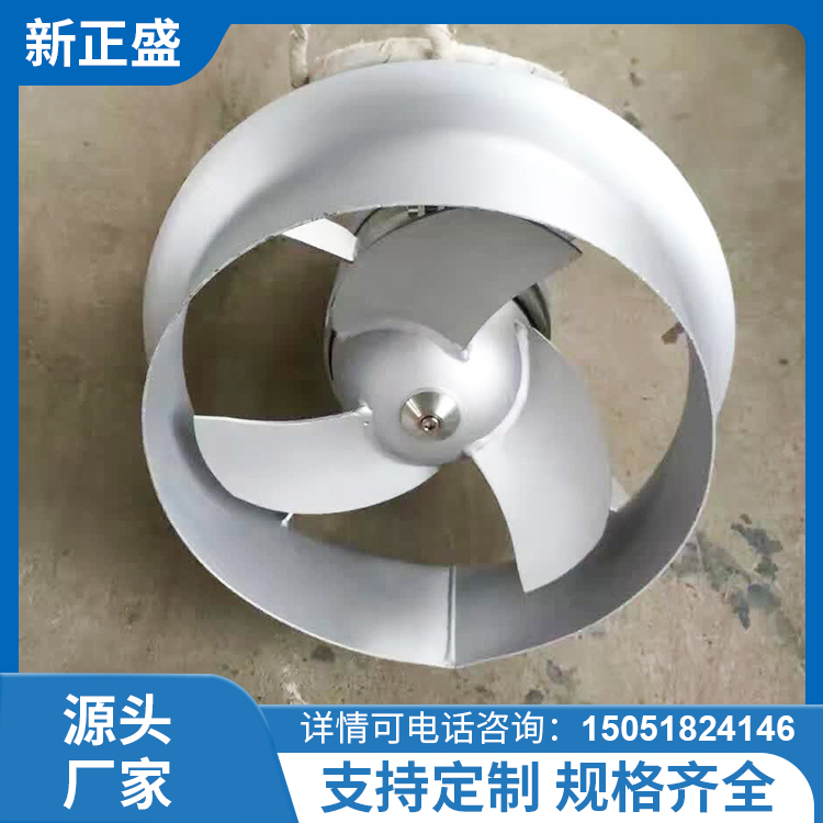
The GSHZ series decontamination machines are widely used in water supply and drainage projects, intercepting floating debris in water or separating impurities, ensuring the safe operation of water pumps and subsequent processes.
Model Representation Method:
GSHZ—————————— 600 x 2
![]()
![]()
![]()
![]()
Channel Depth m
![]()
Equipment Width mm
![]()
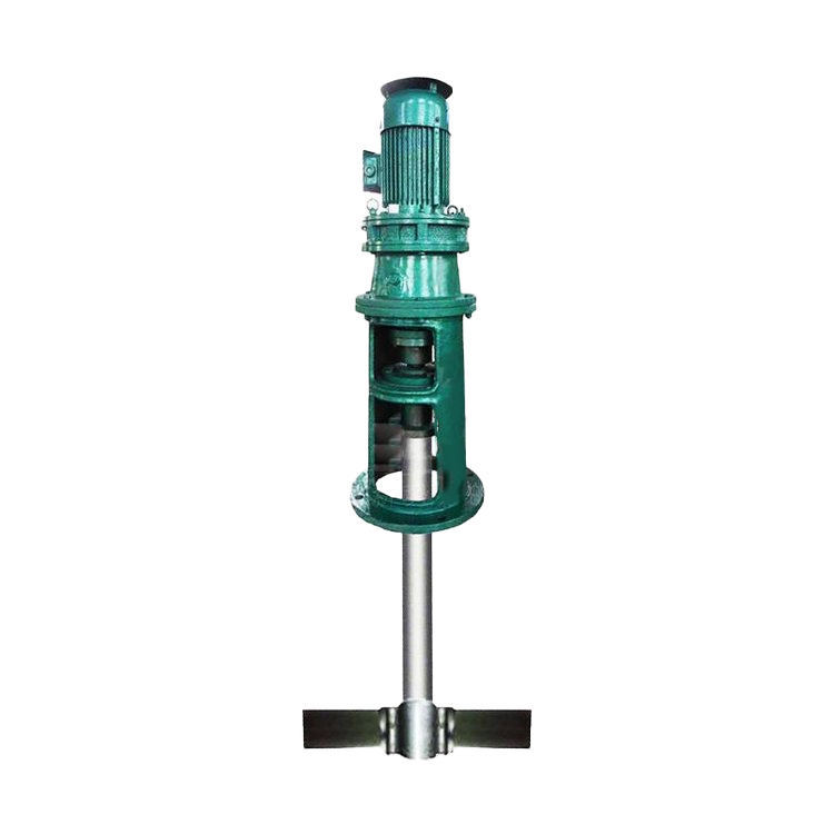
Screw-type格栅Cleaning Machine
2、Product Features:
2.1 Fewer transmission components, simple structure, integrated design, easy to maintain and manage.
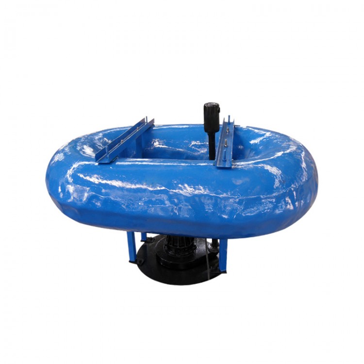
2.2 Excellent corrosion resistance, energy-saving, and low noise.
2.3 ExcludingContinuous dirty action, clean slag removal, high separation efficiency.
3. Construction and Working Process:
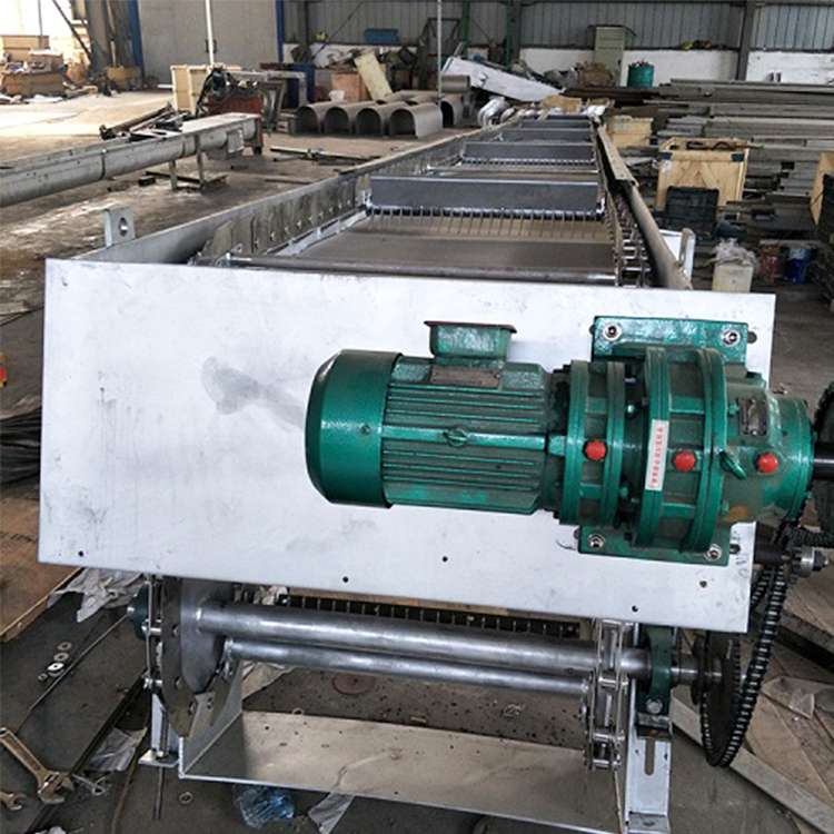
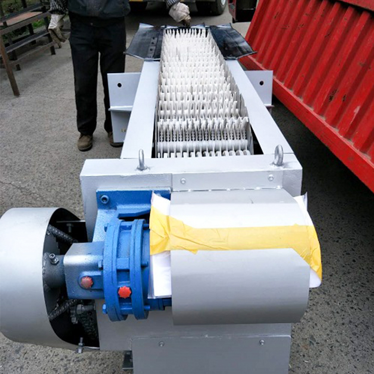
3.1. The rotary grille cleaner is mainly composed of a reducer, frame, rake chain, chain, and baffle.Control cabinets and other components.
3.2 Grilles are designed for outdoor use, capable of operating normally in environmental temperatures ranging from -5 to 40°C. All componentsThe design ensures a long service life in harsh environments.
3.The 3 grates operate intermittently but can also run continuously for 24 hours if necessary.
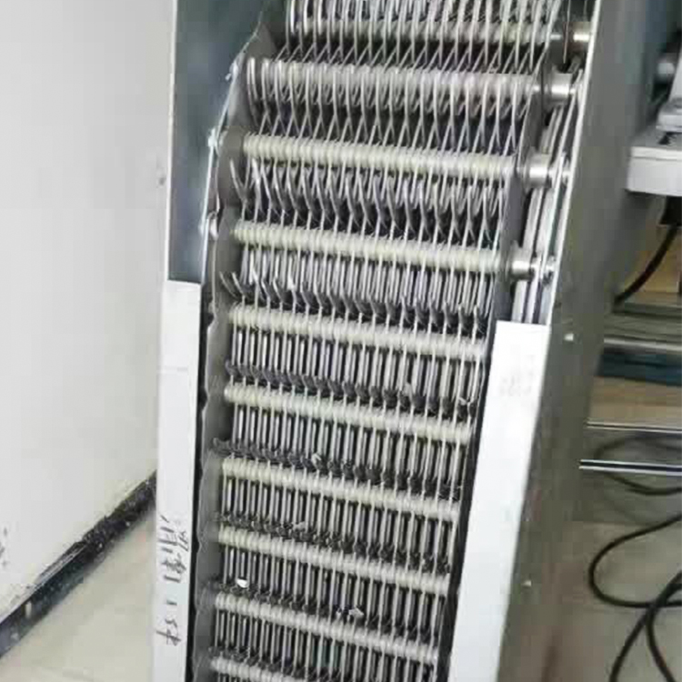
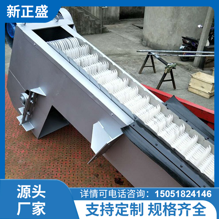
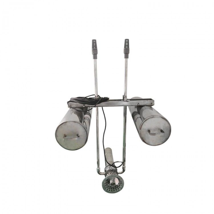
3.The 4-tined chain consists of several groups of special-shaped tines made from stainless steel or nylon, assembled in a specific sequence onto the tine shaft to form a closed-chain tine assembly, with the lower section installed in the water body of the inflow channel. As the drive system moves the sprocket to rotate uniformly and in a fixed direction, the entire tine chain moves from top to bottom, separating solid debris from the liquid. The fluid passes through the gaps between the tines, with the entire working process occurring continuously.
3.5 Due to the special structural shape of the teeth, the rake teeth chain carries debris to the top for reverse movement.The relative self-cleaning movement between the front and rear rake teeth promotes debris to fall off due to gravity, while a pair of rubber brush plates are set at the rear of the equipment to ensure that each row of rake teeth is thoroughly cleaned when they reach that position.
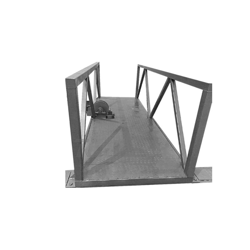
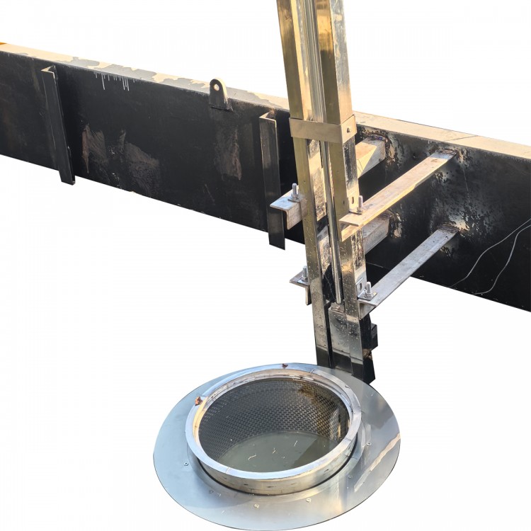
3.6 Grille brackets are securely fastened to both sides of the concrete channel with base bolts, making them easy to disassemble. GrilleThe grate installation ensures that all wastewater within the channel flows through the格栅, eliminating dead zones and preventing garbage from accumulating at the bottom.
3.7-bar grating frames can withstand loads from large floating objects; the rated load of the teeth rake is ≥1000N, inNo significant offset, damage, or deformation during operation with large water level differences.
3.8-grid configuration equipped with a mechanical overload protection device; an alarm is triggered inside the electrical control box upon overload, and it automaticallyPower on/off.
3.The motor drive unit and grille guard are integrated as one, with the motor power supply at 380V, 3-phase, 50Hz.IP ratingIP55, F-grade insulation.
3.10The stainless steel label is securely fastened in a prominent location on the equipment, featuring embossed numbers.Character MarkAmbition.
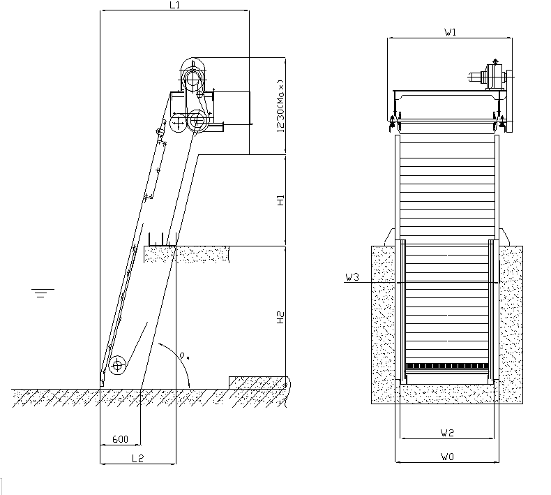
II. Main Technical Parameters and Outline Diagram
Parameter meaning:
W0: Equipment Width
W1: Shape Width
W2: Effective Grid Width
W3: Channel Width
Installation Angle
H1: Channel Depth
H2: Sludge Height
L1: Total Length of Installation
L2: Diverter channel length
Note: The above data can be determined according to customer requirements; see samples and installation diagrams for details.
Section 3: Equipment Installation and Commissioning Requirements
1. Check if the foundation size matches the base size prior to hoisting and installation.
2. After verifying the basic dimensions, place the equipment into the base so that the equipment's center aligns with the center of the grid channel, ensuring the center deviation between them does not exceed 20mm.
3. Remove the safety cover and loosen the tension chain wheel, then detach the sprocket chain at the reducer end. Power on and test the reducer's rotation direction to ensure it's correct.
Adjust the tension of the tension wheel and gear rack.
5. After normal operation under no-load with the power connected, then proceed to operate with the load.
6. In operation, if debris such as fibers block the toothed chain, it should be cleared promptly to prevent affecting the normal operation of the equipment.
7. If the motor operates normally but the gear rack does not, it indicates that the overload has caused the safety pin to break, and the overload safety pin must be replaced.
8. Use grease lubrication for roller bearings and regularly check if there is enough oil. Inject grease through the oil nozzle on the bearing housing using a grease gun.
Four、Reducer maintenance
1. Lubrication Method:
Lubrication Method Chart for Worm Gearbox in Standard Installation Form (see table below):
Lubrication Method | Lubricating oil | ||||||||||
Single-stage | Dual-level | Grade 3 | Ambient Temperature (°C) | Extreme Pressure Gear Oil | ISO Extreme Pressure Gear Oil | ||||||
Model Number | Horizontal Installation | Vertical Mount | Model No. | Horizontal Mount | Vertical Mount | Model Number | Horizontal Mount | Vertical installation | -5-10 | L-CKC68 | EP68 |
B09-2 | Smooth grease | B10-20 | Slick grease | B310 | Slick grease | 0-35 | L-CKC100 L-CKC150 | EP150 | |||
B3-9 | Oil Bath | Lubrication Pump | B31-95 | Oil Bath | Lubrication Pump | B420-953 | Oil bath | Lubrication Pump | 30-50 | L-CKC220 L-CKC320 L-CKC460 | EP220-460 |
Note: When the reducer is lubricated with grease, it is recommended to use 2# lithium grease, 2# extreme pressure lithium grease, or 00# reducer grease.
2. The reducer must be lubricated before use; for ease of assembly and transportation, reducers at the factory are generally not lubricated.
3. The reducer with oil lubrication has been pre-filled with grease before shipment.
4. In harsh working conditions, such as frequent start-stop operations and high or low temperatures, for the operation of the cycloidal pinwheel reducer, re-evaluate the lubricant should be considered.
5. When adding lubricating oil, the oil level should not exceed the upper limit of the oil gauge nor fall below the lower limit. During operation, the oil level should be regularly monitored and replenished with the same brand of oil as needed.
Helical bevel gear reducer with standard installation form, oil and grease filling amount:
Model Type (Horizontal, Vertical) | B09 | B0 | B1 | B2 | B10 | B20 | ||||
Lubricant Quantity (kg) | 0.14 | 0.16 | 0.37 | 0.75 | 0.43 | 0.85 | ||||
Model Number | B3 | B4 | B5 | B6 | B7 | B8 | B9 | B31 | B41 | |
Lubricant Quantity (L) | Lay | 1.4 | 2.2 | 4.5 | 7 | 14 | 30 | 56 | 1.5 | 2.2 |
Please provide the Chinese content you would like translated into American English. | 2.5 | 3.8 | 6 | 11 | 14 | 30 | 60 | 3 | 4 | |
Model Number | B42 | B52 | B53 | B63 | B74 | B84 | B85 | B95 | ||
Lubricant Quantity (L) | Lay | 3.3 | 6 | 6.3 | 10 | 16 | 35 | 36 | 70 | |
Please provide the Chinese content to be translated. | 4 | 6 | 6.5 | 11 | 16 | 35 | 36 | 70 | ||
Note: The amount of lubricating oil for the reducer is based on the oil level indicator; the parameters in the table are for reference only.
6. Lubricant Replacement System:
Replace the DI once, then replace it again after the reducer has operated for the first 300 hours. During replacement, remove any remaining oil. Subsequent replacements: for those working continuously for over 10 hours a day, replace every 3 months; for those working less than 10 hours a day, replace every 6 hours.
7. Oil Change System: Change every 6 months.
8. Prior to restarting a reducer that has been unused for a long time, it is mandatory to replace the lubricating oil or grease.
9. No unclean or corrosive lubricants are allowed.
5. Control Box Installation, Use, and Maintenance
Installation and Usage Instructions:
Rated voltage is 380V, grounding resistance less than 4Ω, the grounding should be safe and reliable.
1. Turn on the electrical control, and close the circuit breaker inside the box.
2. Control by pressing the button on the box door as needed.
3. Do not use time-delayed circuit breakers, and secure the box door.
4. This electrical control box is outdoor type, with IP55 protection class.
Maintenance:
1. Regular inspections of the electrical control box are required to check for loose contacts and to remove dust.
2. If water accidentally enters, discontinue use and allow to air dry or dry naturally.
3. Ensure proper management of the electrical control box, preventing unauthorized access and damage.
4. Maintenance and repairs should be performed by a qualified electrician.