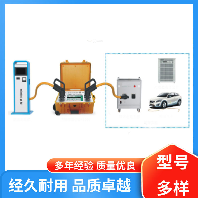


Product Overview
The ED1320 DC Charging Station Field Calibration Instrument is a portable device specifically designed for on-site testing of electric vehicle DC charging machines. It can measure DC voltage up to 1150V and DC current up to 300A, offering three available specifications: 0.02/0.05/0.1 grade. This instrument is suitable for on-site power measurement inspections by计量单位, power departments, and manufacturers, as well as for conduction charging interoperability tests and communication protocol consistency tests.
Reference Standard
GB/T 18487.1-2015 "Conductive Charging System for Electric Vehicles, Part 1: General Requirements"
GB/T 20234.1-2015 "Connection Devices for Conductive Charging of Electric Vehicles, Part 1: General Requirements"
GB/T 20234.3-2015 "Connection Devices for Conductive Charging of Electric Vehicles, Part 3: Direct Current Charging Interface"
GB/T 27930-2015 "Communication Protocol between Electric Vehicle Non-Portable Charging Equipment and Battery Management System"
GB/T 34657.1-2017 "Interoperability Test Specification for Conductive Charging of Electric Vehicles - Part 1: Power Supply Equipment"
GB/T 34658-2017 "Communication Protocol between Electric Vehicle Non-vehicle Charging Equipment and Battery Management System — Conformity Test"
GB/T 29318-2012 "Electric Vehicle Non-Portable Charging Equipment Energy Metering"
JJG 1049–2018 "Regulation for Verification of Non-Portable Charging Equipment for Electric Vehicles"
Product Features
1. Product Features
DC Ripple Measurement: Wide dynamic range, capable of detecting AC ripple below 1 kHz.
Battery Waveform Display: Real-time charging curves U(t), I(t), P(t), E(t) display and record, etc.
Environmental Temperature Measurement: Equipped with a temperature sensor to measure the ambient temperature on-site for correcting working errors.
Clock Calibration Function: Built-in GPS clock module, real-time clock display, and Beijing time synchronization for the charger.
Built-in vehicle control guidance circuit: capable of performing interoperability tests for non-vehicle charging stations, equipped with an R4 resistance simulation module, resistance adjustment range of 400 Ω to 5000 Ω, step of 1 Ω. Each contact point is equipped with a switch for opening and closing, enabling simulation of contact on/off states.
Insulation Resistance Simulation: Enables simulation of charger insulation status, voltage input range 0 V to 1000 V, resistance adjustment range 10 kΩ to 610 kΩ, step size 5 kΩ, used for simulating positive and negative pole insulation faults of charging stations.
2. Key Features
Utilizing wideband AC/DC current comparator technology, the thermoelectric potential influence is minimal compared to shunt resistors, and the accuracy is high.
Direct current measurement (no wiring required), one connection to automatically complete preset test items.
No mechanical contacts like switches or relays in the current circuit; withstands 2 times the rated current without damage for 5 seconds, high reliability.
The current measurement circuit achieves high isolation from the voltage circuit and the power supply, ensuring enhanced safety.
Equipped with dedicated calibration terminals, the device can be calibrated or tested using two methods.
Equipped with a high-definition LCD touch color screen, visible in sunlight, featuring an intuitive interface and easy operation.
Equipped with CAN-BUS, RS232, USB, Ethernet, WiFi interfaces and host computer software, easy for setting up an automatic test system.
Equipped with a portable instrument case, featuring high vibration resistance and electrical protection grade, it is extremely convenient to carry to the site.
3. Inspection Items
Charge Electric Energy Metering Characteristics Verification: Non-vehicle charger working error, charge quantity display error, payment amount error, clock indication error, and other test items.
Conduction Charging Interoperability Tests: Connection Confirmation Tests, Self-Check Stage Tests, Charging Ready Tests, Charging Stage Tests, Normal Charging Completion Tests, Charging Connection Control Timing Tests, Communication Interruption Tests, Switch S Disconnection Tests, Vehicle Interface Disconnection Tests, Output Voltage Exceeding Vehicle Allowance Tests, Insulation Fault Tests, Other Charging Faults, Output Voltage Control Error Tests, Output Current Control Error Tests, Output Current Control Time Tests, Output Current Stopping Rate Tests, Control Guidance Voltage Overlimit Tests, etc.
Consistency Test of Communication Protocols.
Technical Specifications
1. Technical Specifications
Direct Current Voltage Measurement (DCV)
| Range | Resolution | Annual measurement uncertainty (k=2) ( ppm*RD①+ppm*RG②) | Temperature coefficient, ± ppm*RD/°C @-30℃~55℃ | ||||
| 0.1Grade | 0.05Grade | 0.02Grade | 0.1Grade | 0.05Grade | 0.02Grade | ||
| 300 V | 0.1 mV | 400 + 50 | 200 + 25 | 60 + 20 | < 20 | < 10 | < 5 |
| 750 V | 0.1 mV | 400 + 50 | 200 + 25 | 60 + 20 | < 20 | < 10 | < 5 |
| 1000 V | 1 mV | 400 + 50 | 200 + 25 | 60 + 20 | < 20 | < 10 | < 5 |
| Note: ① RD stands for Reading Value, ② RG stands for Range Value, and so on. | |||||||
Measurement Characteristics:
Range: Manual/Automatic Gear Shift
Measurement Range: 30 V to 1150 V
Waveshape Measurement Uncertainty (k = 2): 0.05% of RG RMS; Bandwidth: ≤ 1 kHz
2 Direct Current Measurement (DCI)
| Range | Resolution | Annual measurement uncertainty (k=2) ( ppm*RD+ppm*RG) | Temperature coefficient, ± ppm*RD/°C @-30℃~55℃ | ||||
| 0.1Grade | 0.05Grade | 0.02Grade | 0.1Grade | 0.05Grade | 0.02Grade | ||
| 5 A | 1 μA | 1500 + 800 | 1000 + 800 | 800 + 600 | 150 | 100 | 50 |
| 10 A | 10 μA | 800 + 400 | 500 + 400 | 400 + 300 | 80 | 50 | 25 |
| 20 A | 10 μA | 600 + 300 | 400 + 200 | 300 + 150 | 50 | 30 | 15 |
| 50 A | 10 μA | 500 + 150 | 200 + 75 | 100 + 50 | 30 | 20 | 10 |
| 100 A | 0.1 mA | 400 + 100 | 200 + 50 | 90 + 30 | 20 | 10 | 5 |
| 250 A | 0.1 mA | 400 + 100 | 200 + 50 | 90 + 30 | 20 | 10 | 5 |
Measurement Characteristics:
Range: Manual/Automatic Gear Shift.
Measurement Range: 0.5 A to 300 A
Waveshape Measurement Uncertainty (k = 2): 0.05% of RG RMS; Bandwidth: ≤ 1 kHz
3 DC Power/Electricity Measurement
Power/Energy Measurement Range: Combination of DC Voltage and DC Current
Power/Electricity Uncertainty = Voltage Uncertainty + Current Uncertainty
Standard electrical pulse output: High frequency of 60 kHz
Supports active and passive pulses, load capacity: greater than 20 mA
Standard electrical pulse input: Frequency - 100 kHz, Level - 0~5V
l Power Error Display Digits: 7 Decimal Digits Display
2. General Technical Specifications
Power Supply: AC (198 V ~ 253 V), (50 ± 2) Hz; Power Consumption: ~80 VA
Work Environment: -30℃ to 55℃, 20% to 80% RH, no condensation
Storage Environment: -30°C to 70°C, <80% R·H, no condensation
Unit dimensions: 560 mm (W) × 460 mm (D) × 260 mm (H)
Unit Weight: Approximately 28.0 kg
Communication Interfaces: CAN-BUS, RS232, USB, Ethernet, WIFI