


1. Measurement Principle
Principle:
High-frequency microwave pulses emitted by the waveguide radar propagate along the detection component (steel cable or steel rod) and, upon encountering the medium being measured, are reflected due to a sudden change in dielectric constant. A portion of the pulse energy is reflected back. The time interval between the transmitted and reflected pulses is proportional to the distance of the medium being measured.
Features:
Due to the use of advanced microprocessors and the unique choDiscovery echo processing technology, guided wave radar level gauges can be applied to various complex operating conditions. The diverse process connection methods and probe components make the 60X series guided wave radar level gauges suitable for a wide range of complex operating conditions and applications, such as high temperature, high pressure, and low dielectric constant media.
Pulse-mode operation ensures low power emission in the guided wave radar level gauge, suitable for installation in various metallic and non-metallic containers without harm to humans or the environment.
Description:
The waveguide radar is a measuring instrument based on the time-of-flight principle. Radar waves travel at the speed of light, and their travel time can be converted into level signals by electronic components. The probe emits high-frequency pulses, which propagate along cable or rod probes. When the pulses encounter the material surface, they are reflected back and received by the receiver within the instrument, converting the distance signal into a level signal.
Reflective pulse signals are conducted to the instrument's electronic circuitry via cable or rod probes, where a microprocessor processes the signal to identify echoes generated by microwave pulses on the material surface. Correct echo signal identification is performed by the pulse software, with the distance D from the material surface being directly proportional to the pulse's travel time T: D = C × T/2.
If the distance E to the empty drum is known and C is the speed of light, then the level L is: L = E - D
2. Technical Specifications:
*Large Range/Probe Type:6000mm / Coaxial Tube Antenna
License:
P Standard Type (Non-Explosion Proof)
intrinsically safe (Exia IC T6Ga)
Type 4 Intrinsically Safe + Explosion-Proof (Exd(iA)ⅡCT6 Gb)
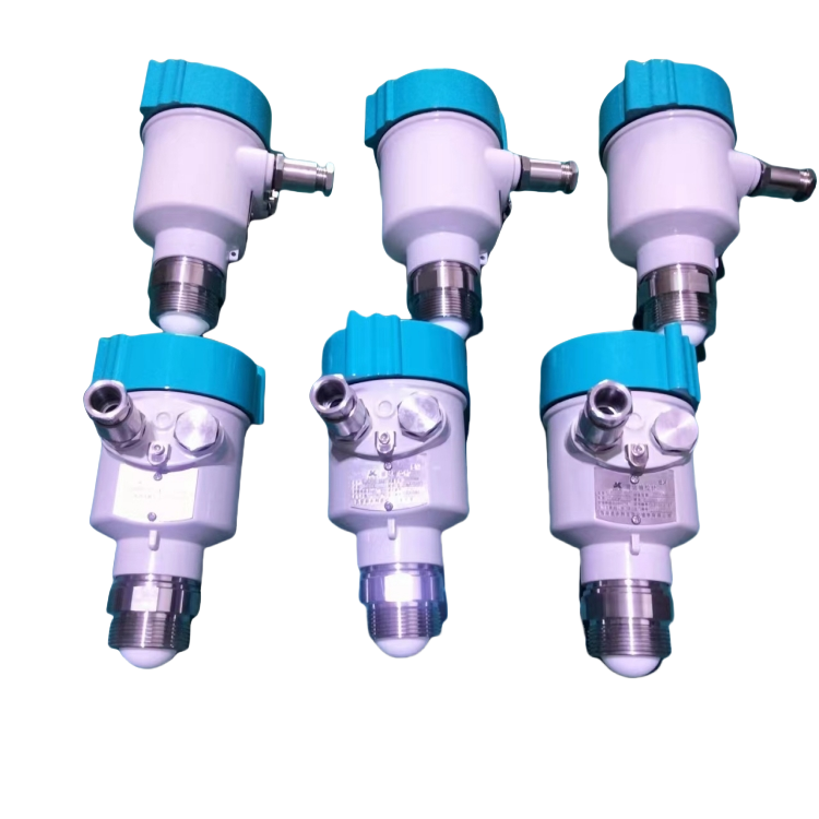
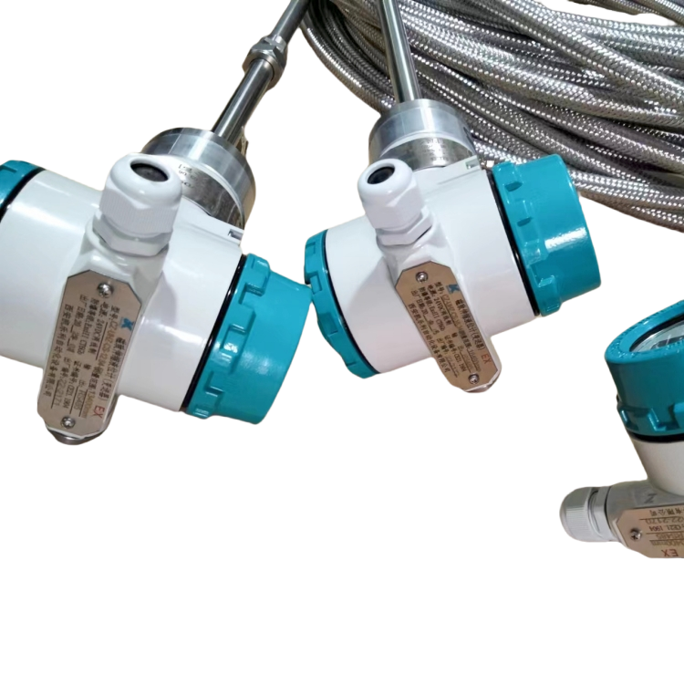
Probe Type/Material:
A Cable Type Transducer, 25mm/304 Stainless Steel
B cable probe 25mm / stainless steel 316L
Process Connection:
G Thread G k" A
NPT 1% Thread
C Flange DN50 PN16C/SS
Flange DN80, PN16C/SS
E Flange DN100 PN16C/SS
F Flange DN150 PN16C/SS
H Flange 2" 150LBS ANSI Raised Face/Stainless Steel 316L
Flange 3" 150LBS ANSI Raised Face/Stainless Steel 316L
J Flange 4" 150LBS ANSI Raised Face/316L Stainless Steel
6" K-Face Flange 150 lbs ANSI Raised Face/316L Stainless Steel
L Special Customization
Sealed/Process Temperature:
Standard Type (-40~130)℃
2. High-Temperature Type (-40~250)°C
Shell/Protection Class:
L Error/P67
Q Plastic/TP65
Cable entry:
M 20x1.5
N ”NPT
On-site Display:
V-Belt
X without
Programmer:
V-belt
X without


