


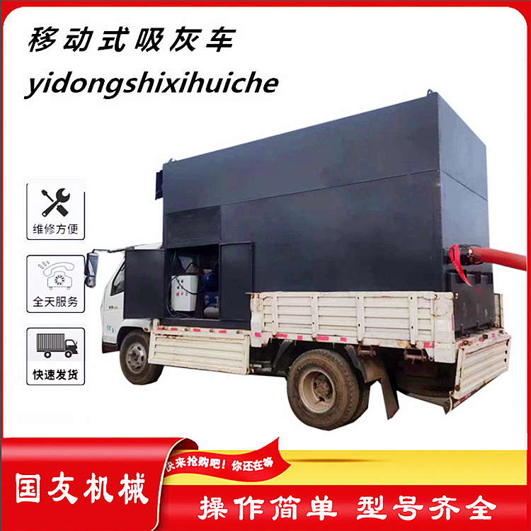
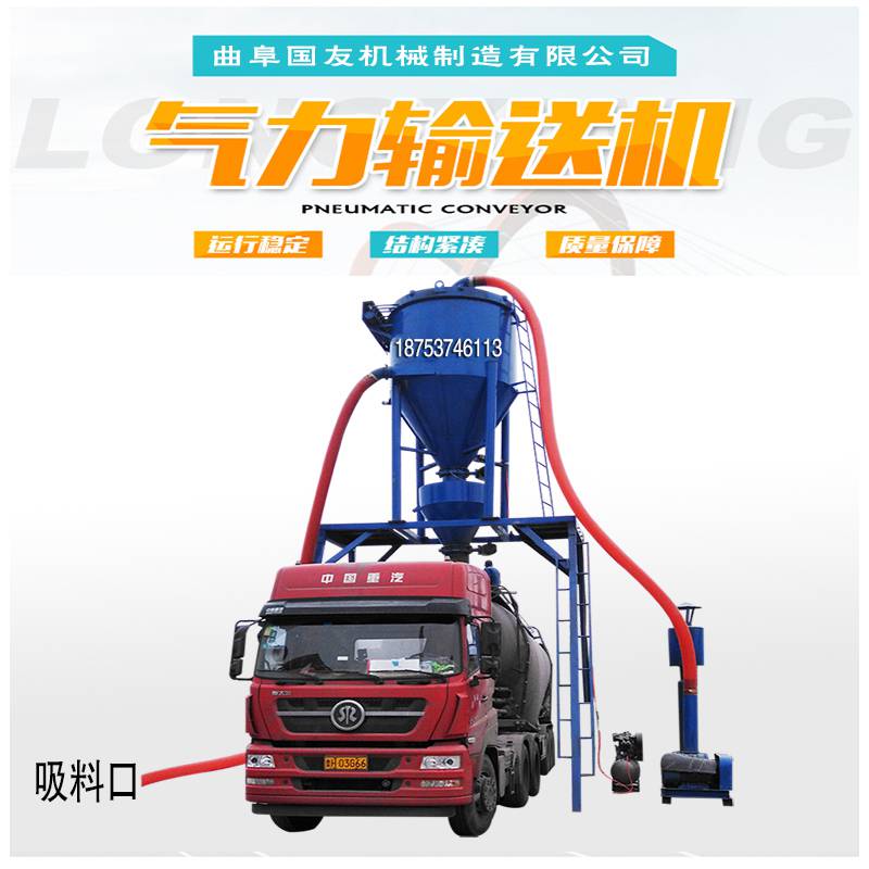
Air Blower Conveyer
Equipment Introduction
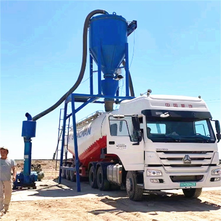
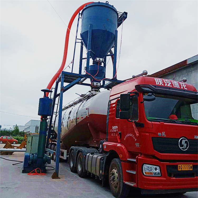
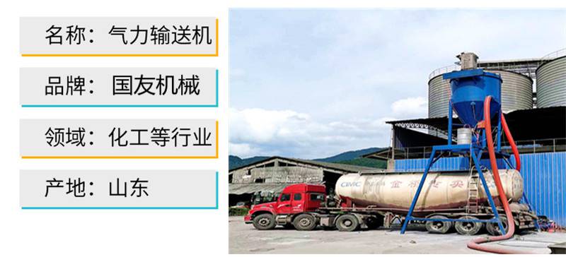
Pulse-jet deduster type pneumatic conveying machine is a unit suitable for fly ash,Self-priming environmental-friendly conveying equipment for the handling and transportation of dry powdery materials such as cement powder, stone powder, activated carbon powder, etc.
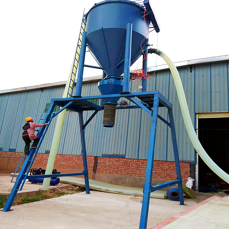
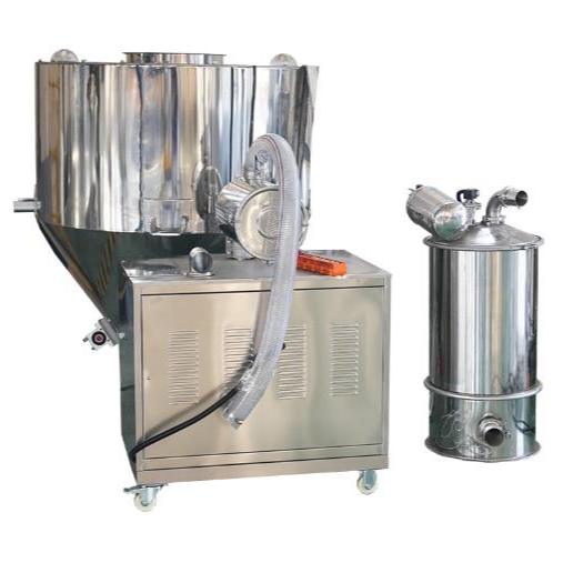
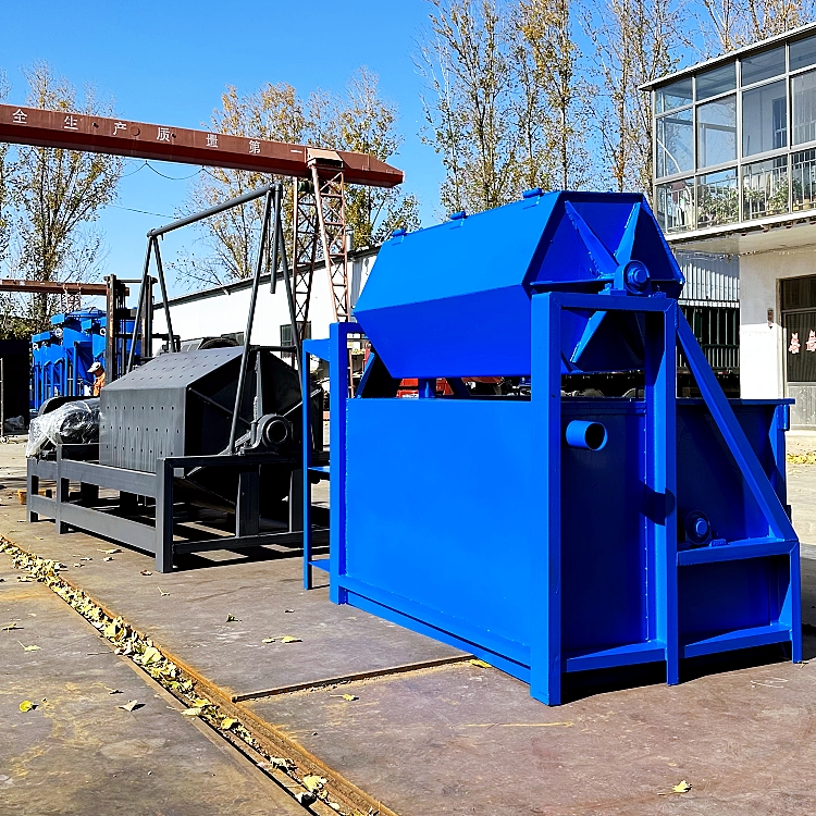
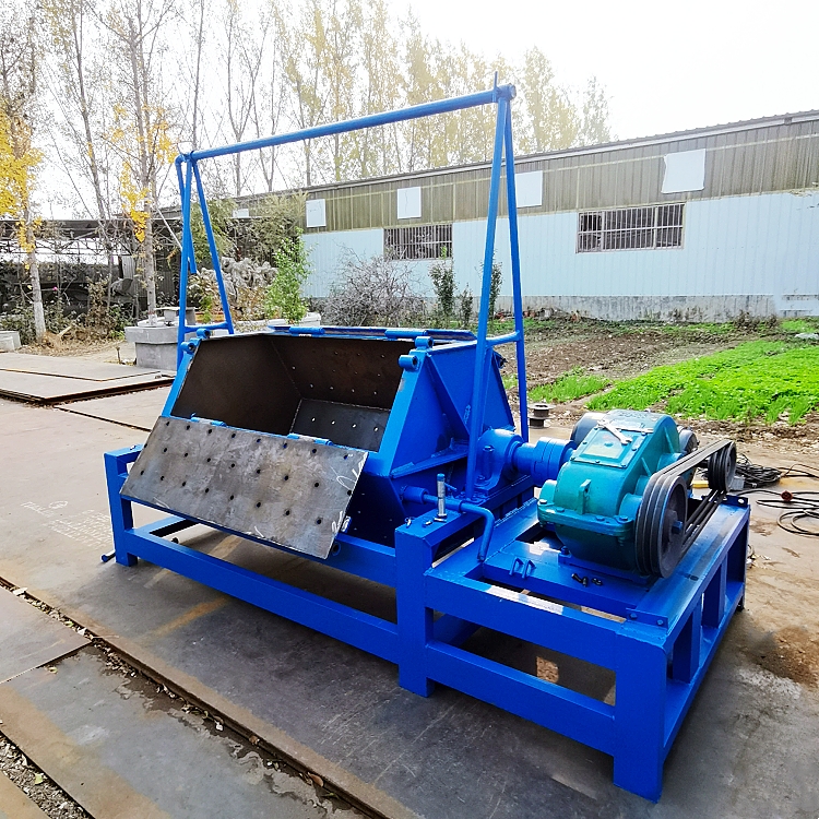
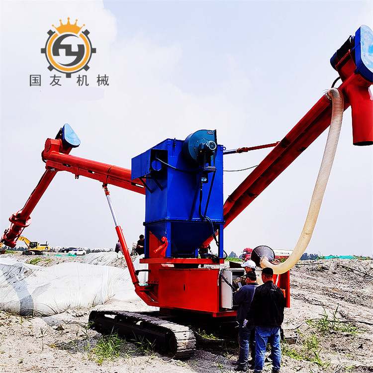
The machine is composed of several parts, including the core (material intake) system (Roots blower, motor, or diesel engine, muffler, base, etc.); the dust removal system (pulsating tank, ladder, air pump, etc.); the unloading system (closed or gravity unloader); the support system (gantry support); the conveying system (rubber hose, connecting short pipe, clamp, etc.); and the accessory system (suction nozzle, telescopic fabric bag, material level switch, etc.).
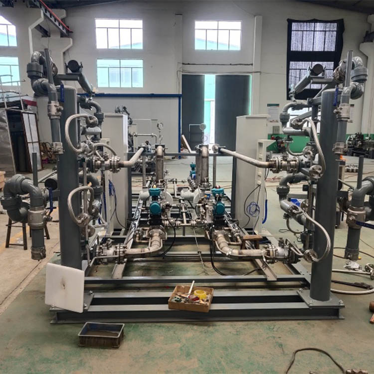
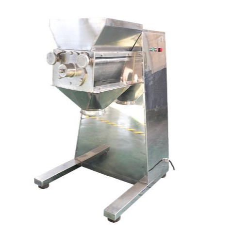
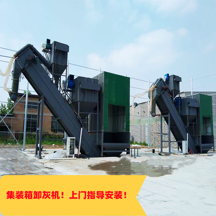
In addition, our company offers a range of auxiliary equipment including robotic arms, rotary feeders, spiral feeders, large capacity hoppers, circular maintenance platforms, variable frequency start cabinets, container unloading systems, and custom processing services for various non-standard pneumatic machines.
The machine comes in various types and specifications, categorized according to different standards.
The unit is available in models with diameters of 100mm, 125, 150, 200, 250, 300, and so on, according to the fan's aperture.
Various models of fans are paired with corresponding motors/diesel engines, air compressors, dust collectors, shut-off valves/pneumatic valves, and hoses to achieve different conveying effects.
Application/Field of Use
Fine Chemicals: Pigments, dyes, paints, carbon black, iron oxide, ceramic powder, heavy calcium carbonate, light calcium carbonate, bentonite, molecular sieve, kaolin, silica powder, activated carbon, etc.
Building Materials: Cement, clay, yellow sand, quartz sand, clay powder, silica stone, limestone powder, dolomite powder, wood shavings powder, glass fiber, silicon dioxide, talcum powder, etc.
Food Industry: Flour, starch, grains, milk powder, food additives, etc.
Uncommon materials available for special customization; dust and particles can be separated.
The main features of pneumatic conveying are large conveying capacity, long conveying distance, and high conveying speed; it allows for loading at one location and unloading at multiple locations.
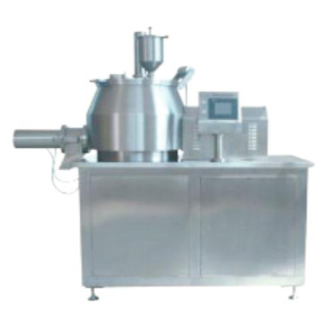
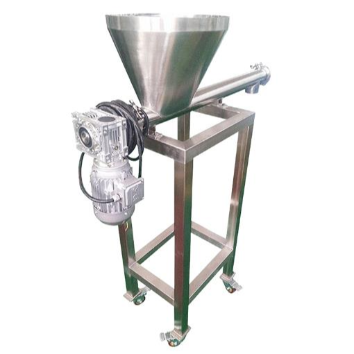
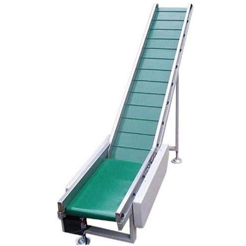
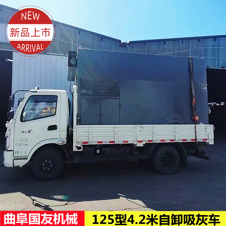
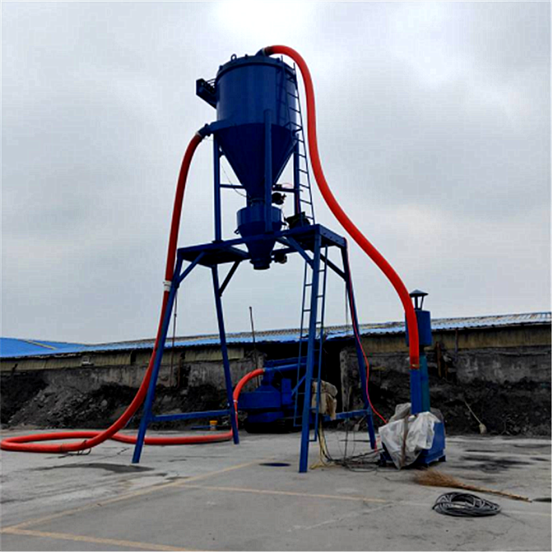
Product Showcase


Suction and delivery features
1. Suitable for concentrating material from several points to one location. The feeding point can be one or several, and the material tube can accommodate one or several.Root pipe. Not only can it sequentially deliver materials from several points.
Discharge points, and can also handle multiple supply points simultaneously.Material is conveyed to the unloading point.
2. Under vacuum, materials are easily吸入, hence the feeding at the throat is straightforward. The hopper can be left open, allowing for easy access.Continuous supply and conveyance.
3. Materials are conveyed under vacuum, making moisture easy to evaporate. Therefore, it is easier to transport materials with higher moisture content compared to pressure conveying.Deliver; For materials supplied under heating conditions, conveyance can be effective.
Cooling effect.
4. Components must maintain a sealed condition; the construction of components such as the gas separator, dust collector, and lock-gas valve is relatively complex.
5. The fan is located at the system terminal, requiring high air purification levels.
Pressure characteristics
1. Suitable for distributing to multiple locations from one point. In other words, there is one feeding point while the unloading points can be one or more.A few.
2. Compared to suction-and-convey systems, concentration and conveying distance can be significantly increased.
3. Under positive pressure, materials are easily discharged from the discharge port, thus the separator and dust collector designs are simple, usually notNeed a lock wind device.
4. Blowers or air compressors at the system's upstream, with low requirements for air purification.
5. Under positive pressure, materials are less likely to enter the conveying pipe, thus making the feeding device's structure more complex.


Equipment Classification
There are three types of pneumatic conveying devices:
(1) Suction and conveying pneumatic conveying system (under vacuum), which creates a vacuum in the pipeline by a blower, causing the pieces of material to move.
(2) Positive pressure pneumatic conveying system, where the material moves within the pipeline due to the action of compressed air.
(3) Mixed-pressure pneumatic conveying system (positive pressure and negative pressure), where part of the conveying pipeline is in a pressurized state, while the other part is under negative pressure, or the material moves in one direction under pressure, and the return movement is driven by the negative pressure within the pipeline.
According to the size of the required pressure, the pneumatic conveying devices can be further divided into:
Low-pressure pneumatic conveying unit — Below 10 kPa
Medium pressure pneumatic conveying equipment – below 50 kPa
High-pressure pneumatic conveying equipment — above 50 kPa
When air compressors are used in the production of gas-lift pumps, pressures can reach 200-300 kPa, even higher.
Low-pressure pneumatic conveying systems are used for the transport of packaged unit loads without intermediate bulk containers, where the conveying distance is limited (either within a standalone production facility or within the scope of an administrative building). Such systems are typically suction-type.
Medium and high-pressure pneumatic conveying systems are used for transporting packaged materials over long distances (200-300 meters and above).
Based on the connection characteristics of the receiving and dispatching stations or loading and unloading stations, pneumatic conveying systems can be categorized as single-tube, double-tube (multi-tube), linear, or circular. A single-tube linear pneumatic conveying system sequentially connects two or several conveying points. Materials can be conveyed in both forward and reverse directions, or simply in one direction.


Installation Steps:
1、Fan, Prime MoverTypically, both are assembled at the factory; upon receipt, simply check the connection points.
2. Pulsating tank.Generally, this section is in a horizontal transportation state. After unloading, there's no need to rush into an upright position. First, inspect the connection points of its components; look inside from the bottom of the tank to check if there are any filter bags that have come off (due to horizontal transportation, this is a normal occurrence); check if the pulse instrument has water inside; and verify if the flange elbow at the top or side feeding opening of the tank is installed (for ease of transportation, it may be removed for shipment). Once these preparations are complete, the pulse tank should be stood upright, ensuring the foundation is solid.
3. Shut-off valve.Secure the shut-off valve to the pulse tank with screws (our company will decide whether to install it upon shipment based on transportation conditions). When securing, consider the position of the shut-off valve motor and junction box for ease of use. Note: Some models come with a shut-off valve flange ring, which should be securely fastened.
4. Base.Blow-exhaust integrated equipment; at this point, the pulsating tank can be mounted on the base. When mounting, consider the location of the feed port.
5. Crane jib.Typically, a gantry is composed of 1 base, 4 square tube legs, 2 square tube crossbeams, and 4 channel steel diagonal struts, which can be secured with screws, and then the pulse tank is placed on top.
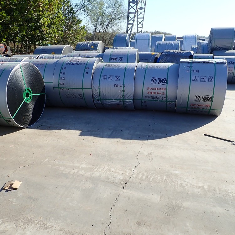
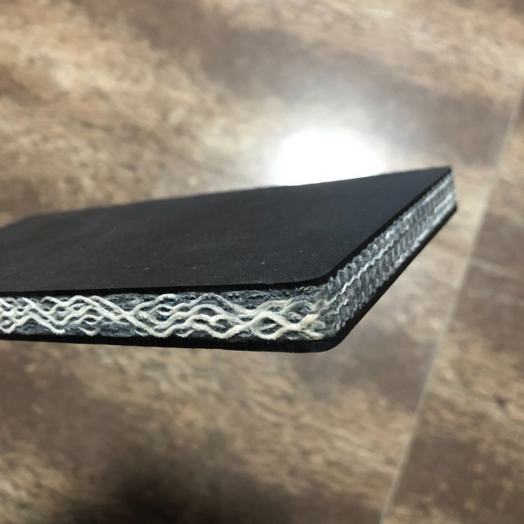
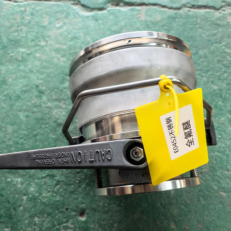
6. Pipes.First, connect the silencer and steel pipe to the fan (for some models, a steel pipe is also required on the pulse tank), then use a shorter flexible hose to connect the fan steel pipe to the bent pipe on top (or side) of the pulse tank, and install the in/out feed hoses. Note: You can heat-treat the hose connection to soften it for easy insertion and removal. After installing the hoses, use clamps to secure them.
7. NozzleConnect with the feeding hose.
8. Air Pump.Use with the same pulse tank, simply connect to the pulse valve.
9. Other.When the total power of the equipment exceeds 30Kw, it should be ensured that the local area has the corresponding power supply capacity and is equipped with soft-start devices such as variable frequency starters.
After completing all these steps, your beloved device is ready for use!