


Product Introduction
A hydraulic coupling is a mechanical device that transfers rotational speed using a liquid medium. It connects the drive input shaft end to the original drive and the driven output shaft end to the load shaft end, altering the output shaft's speed by adjusting the pressure of the liquid medium. In an ideal state, as the pressure approaches infinity, the output speed equals the input speed, similar to a rigid coupling. As the pressure decreases, the output speed correspondingly lowers; continuously altering the medium pressure allows for stepless adjustment of the output speed below the input speed. The principle of power control and speed regulation of a hydraulic coupling, along with its efficiency, is based on its aforementioned characteristics. A hydraulic coupler is a type of energy-consuming mechanical speed control device; the deeper the speed regulation (the lower the speed), the greater the loss, particularly for constant torque loads. Since the original drive input power remains unchanged, the loss of power increases proportionally with the speed loss. For loads like fans and pumps, as the load torque varies with the square of the speed, the original drive input power decreases with the square of the speed, resulting in relatively less power loss. However, the output power decreases cubically with the speed, and the speed regulation efficiency remains low. The speed regulation efficiency curve of a hydraulic coupling shows an average efficiency of around 50%. A non-rigid coupling that operates with a liquid as the working medium, also known as a hydraulic coupling.
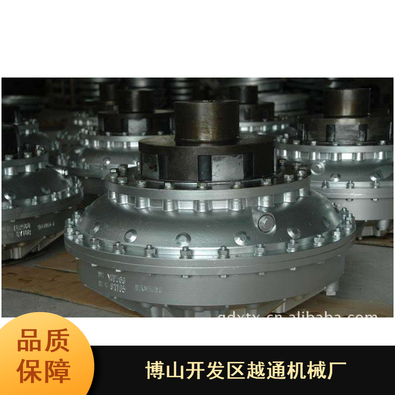
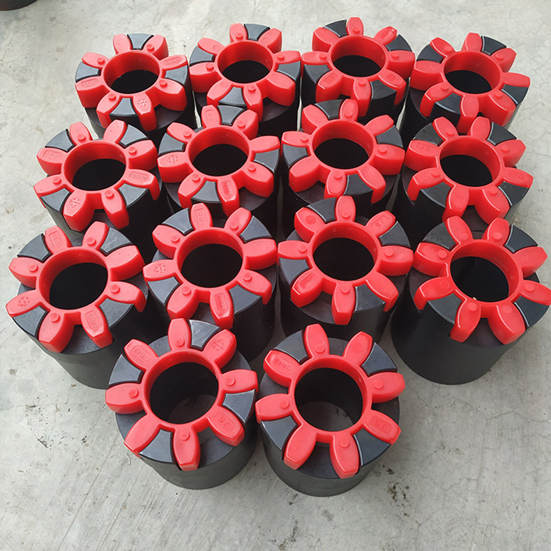
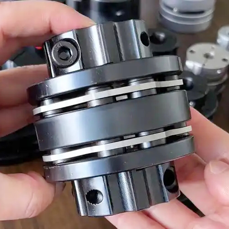
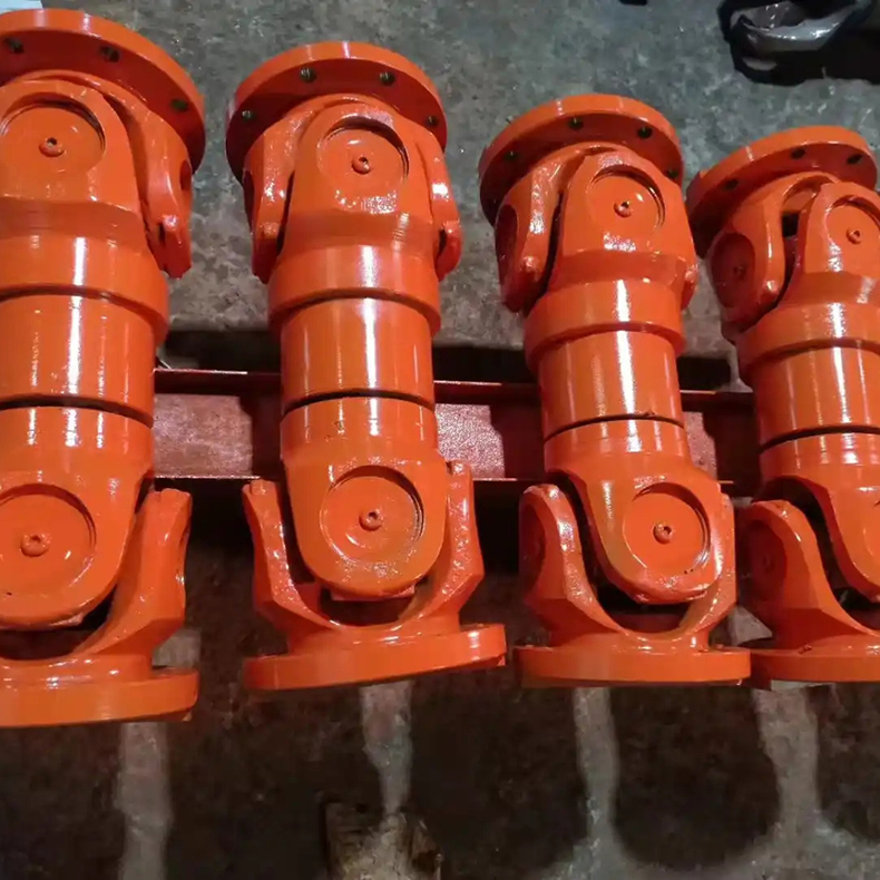
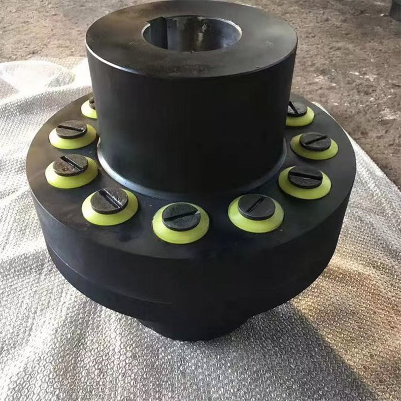
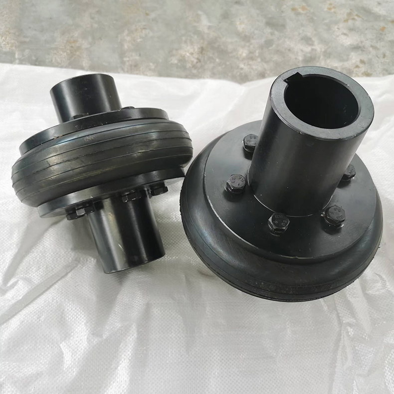
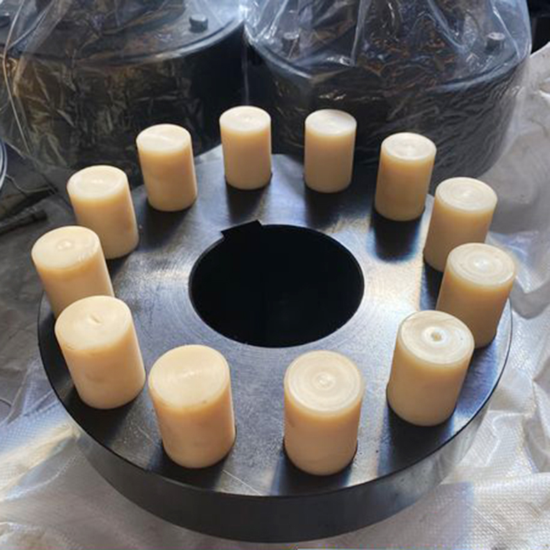
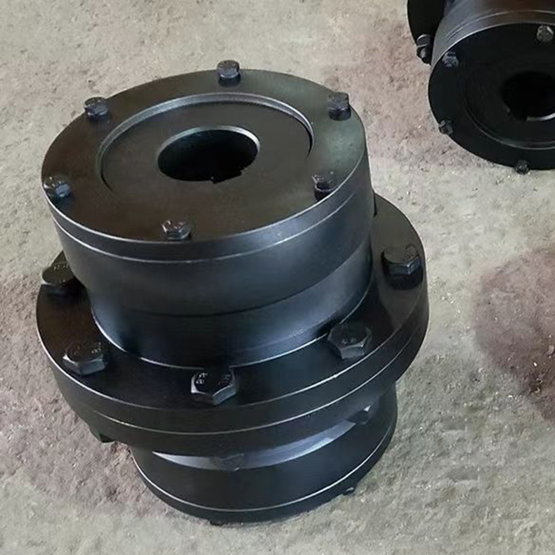
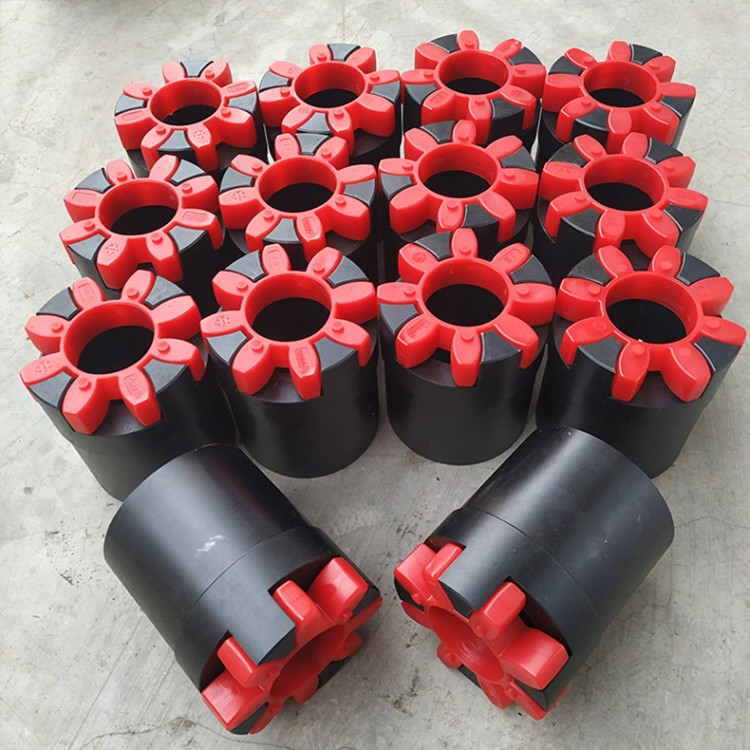
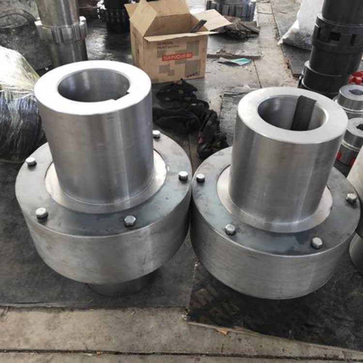
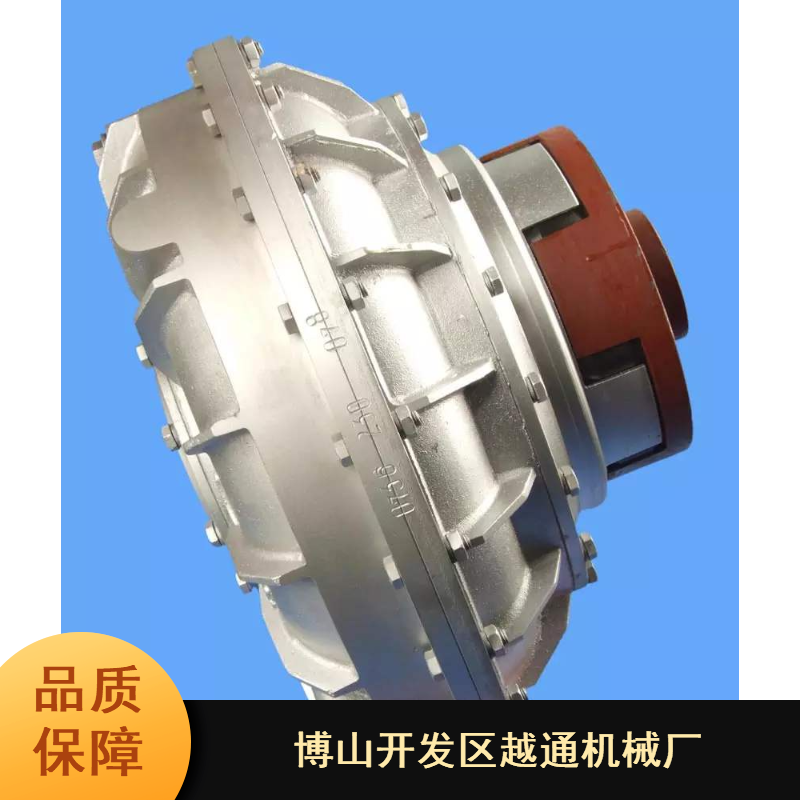
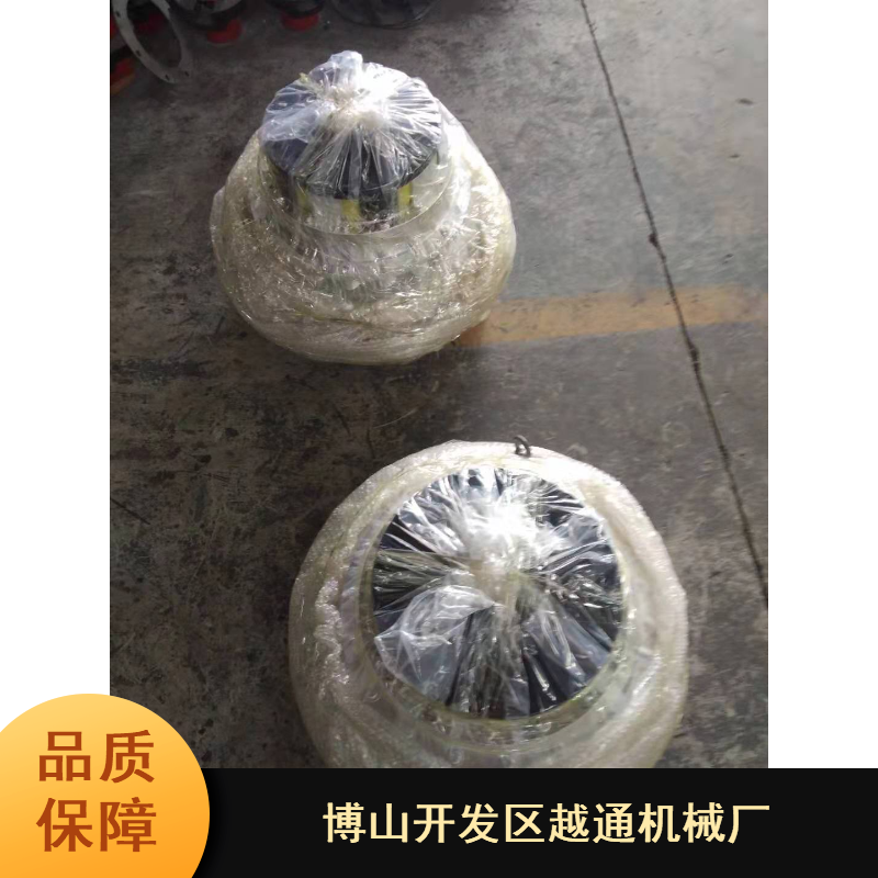
Product Real Photos
Product Features
The impeller and turbine of a hydraulic coupler form a sealed working chamber that allows for the circulating flow of liquid. The impeller is mounted on the input shaft, while the turbine is mounted on the output shaft. As the power source (internal combustion engine, electric motor, etc.) rotates the input shaft, the liquid is ejected by the centrifugal impeller. This high-speed liquid enters the turbine, causing it to rotate and transferring the energy obtained from the impeller to the output shaft. The liquid then returns to the impeller, creating a continuous cycle. The hydraulic coupler transmits torque by changing the momentum moment through the interaction of the liquid with the blades of the impeller and turbine. Its output torque is equal to the input torque minus the friction torque, hence it is always less than the input torque. The input and output shafts of the hydraulic coupler are connected by the liquid, and there is no rigid connection between the working components. The hydraulic coupler features: it can eliminate shock and vibration; the output speed is lower than the input speed, and the speed difference between the two shafts increases with the load; it has good overload protection and starting performance; the input shaft can still rotate when the load is too heavy and the system stops, preventing damage to the power source; when the load decreases, the output shaft speed increases until it approaches the input shaft speed. The transmission efficiency of the hydraulic coupler is equal to the ratio of the output shaft speed multiplied by the output torque (output power) to the input shaft speed multiplied by the input torque (input power). Generally, a hydraulic coupler can achieve higher efficiency when the normal operating speed ratio is above 0.95. The characteristics of the hydraulic coupler vary due to the different shapes of the working chamber and the impeller and turbine. If the oil in the hydraulic coupler is drained, the coupler is disengaged, acting as a clutch.