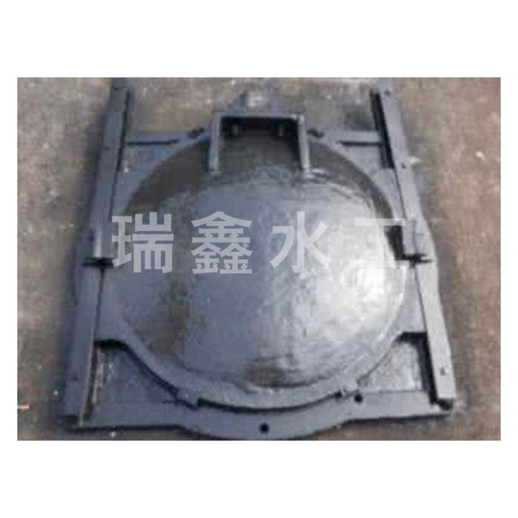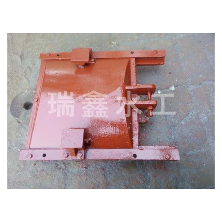


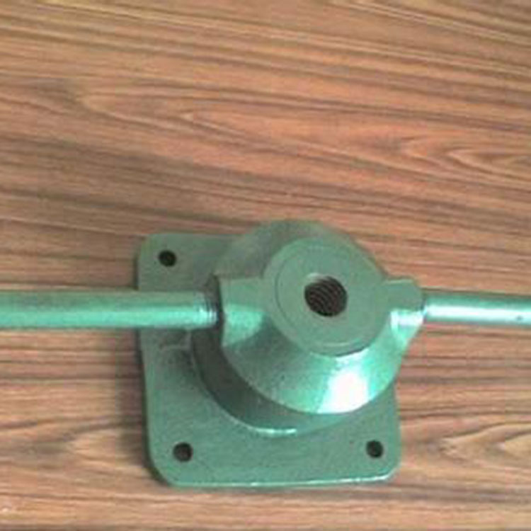


Irrigation gate for paddy fields, characterized by: the bracket (4) is equipped with a motor (5), a linkage mechanism (6), and a stroke switch (7). The linkage mechanism (6) consists of a di-one linkage (61) and a di-two linkage (62), where the di-one linkage (61) has one end fitted onto the output shaft of the motor (5), and the di-two linkage (62) has its ends pivotally connected to the ends of the di-one linkage (61) and the force arm (8). The motor (5) and the stroke switch (7) are fixed on the bracket 4. The lower face of the stroke switch (7) features a horizontal position stop switch (71), and the inner face of the stroke switch (7) is equipped with a vertical position stop switch (72).
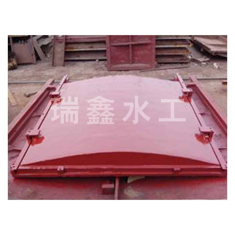
Shut off gate: Start the motor, which rotates the three-link mechanism. The linkage mechanism, with the power arm, lifts the free end of the gate above the water level. When the free end of the gate is horizontal, the power arm contacts the horizontal position of the travel switch and stops the switch, halting the motor. The free end of the gate remains above the water level stationary. At this point, the gate is closed, preventing water from flowing from the bellows hose to the rigid conduit, and thus, it cannot reach the next rice field.
3. Open the Gate: Activate the motor to rotate, which drives the linkage mechanism to continue rotating in the same direction. The free end of the linkage mechanism, connected to the arm of the gate, lowers. The free end of the gate is perpendicular to the ground. At this point, the arm touches the vertical position of the stroke switch, stopping the motor; the free end of the gate remains submerged under the water surface without movement. At this stage, the gate is open, allowing the water channel to flow into the rigid conduit and then into the next rice field.