


Handheld/Lever Double-Action Screw Type Gate Operators, Product Introduction and Installation/Maintenance of Screw Type Gate Operators
I. Introduction to the two-in-one handlamp screw jack for opening and closing
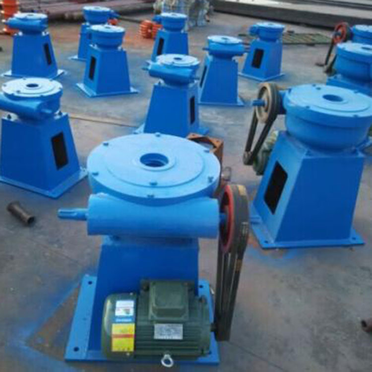
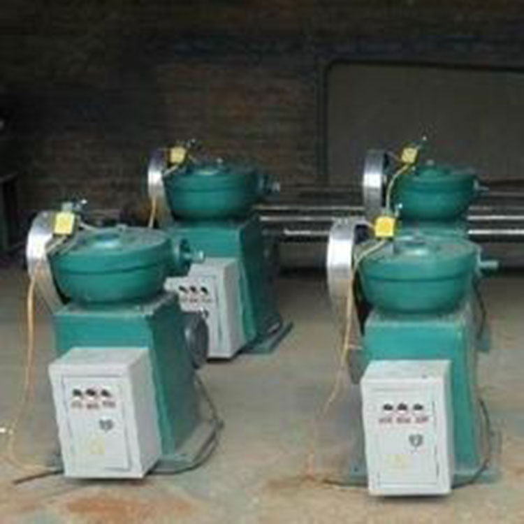
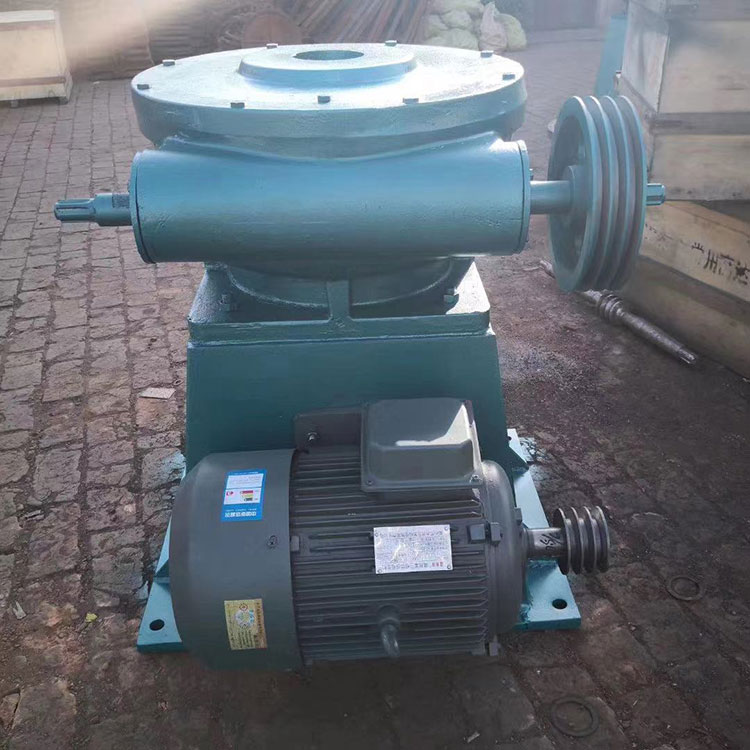
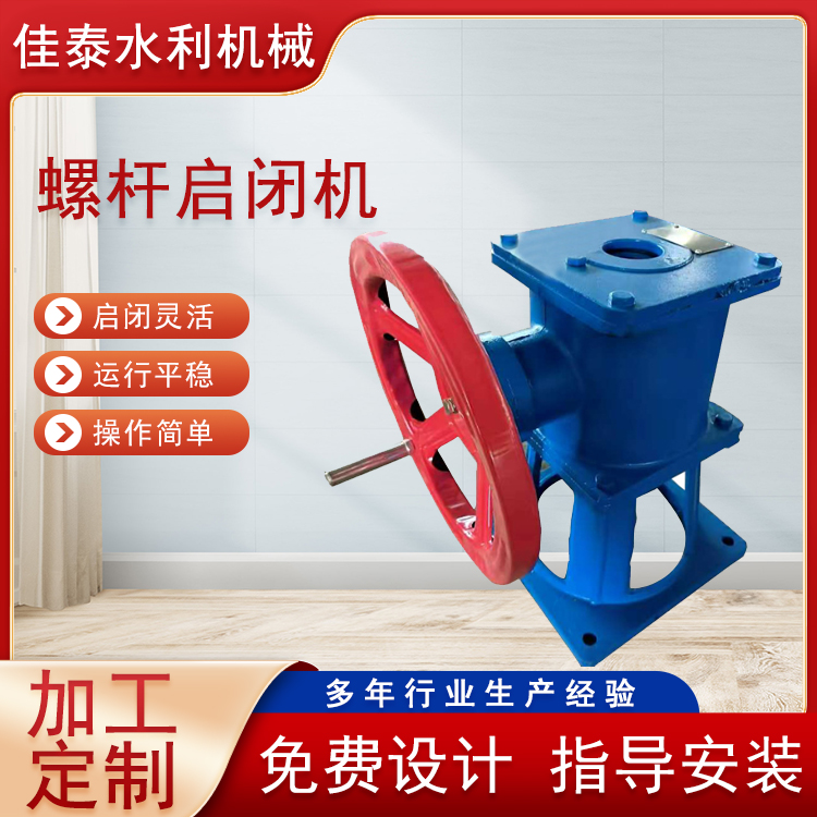
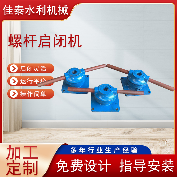
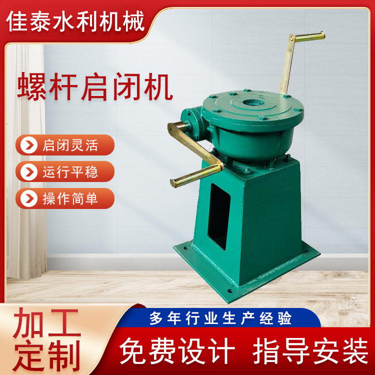
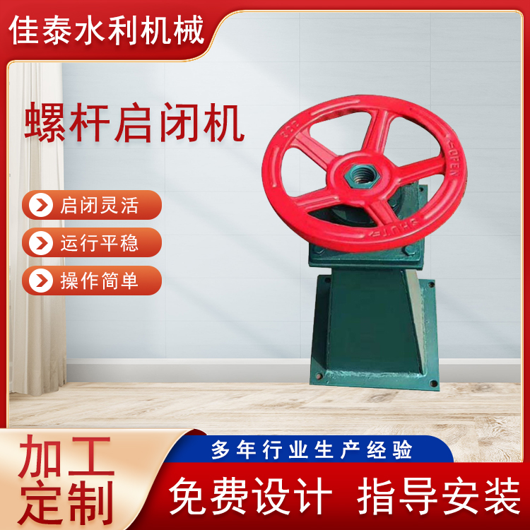
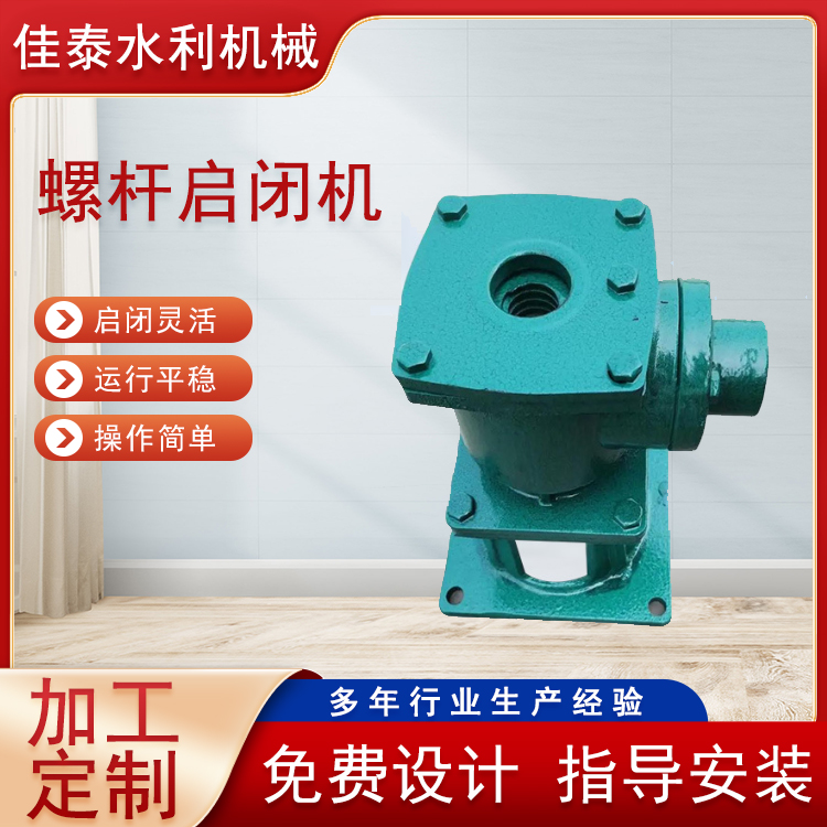
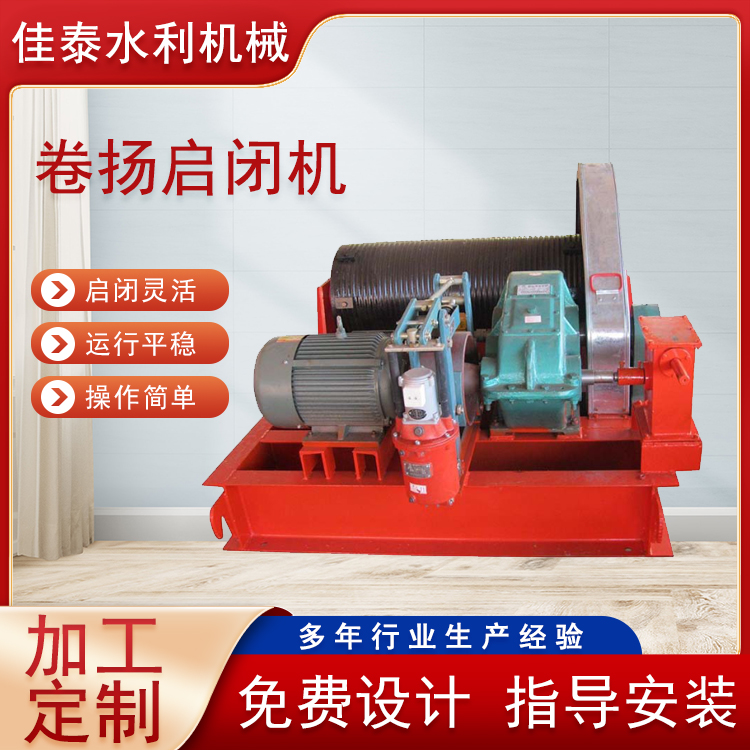
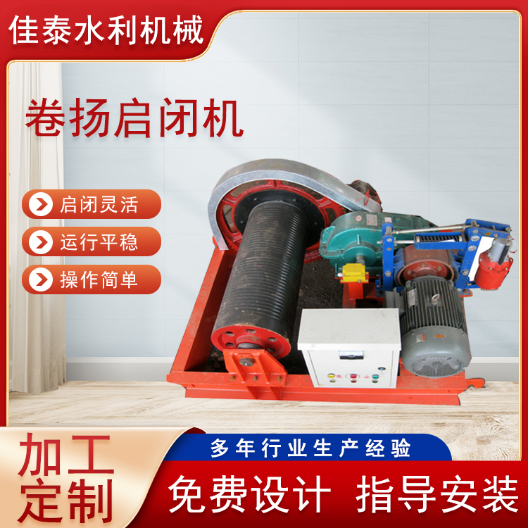
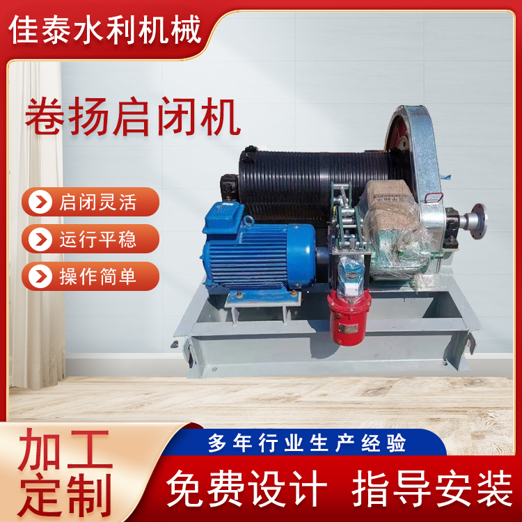
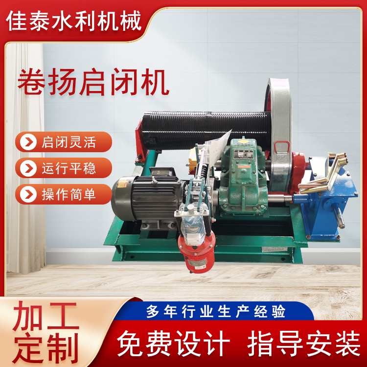
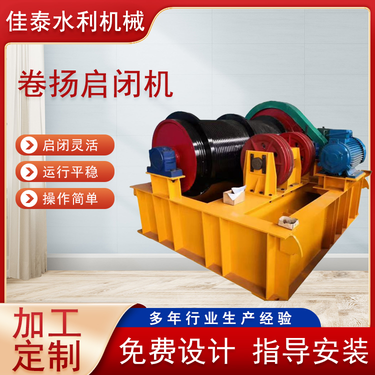
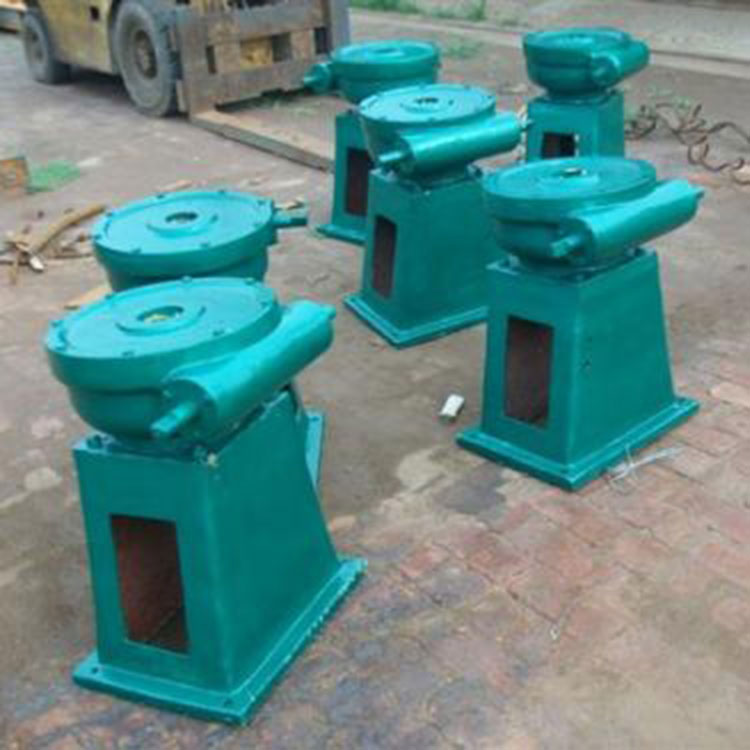
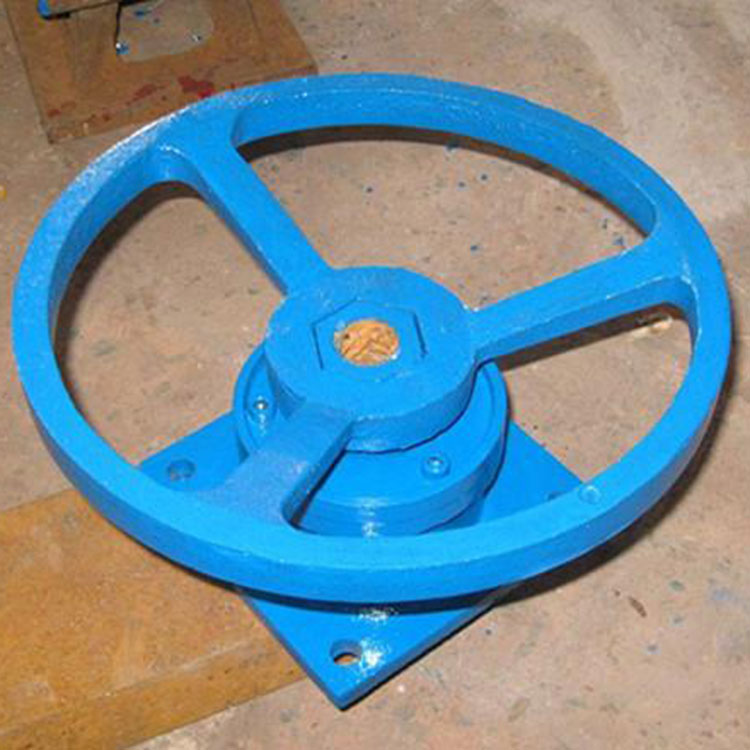
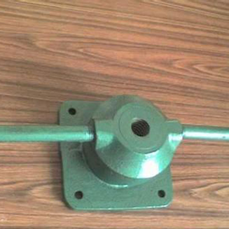
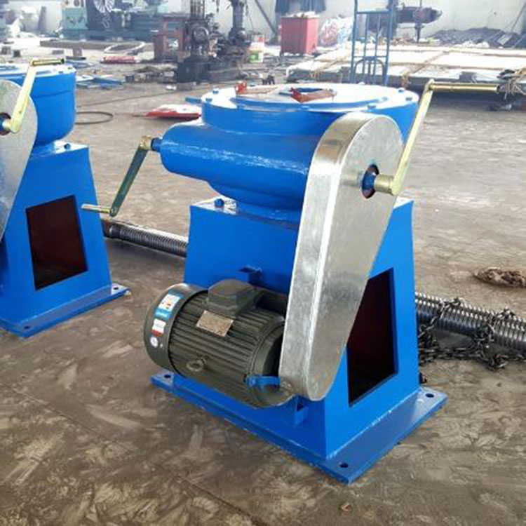
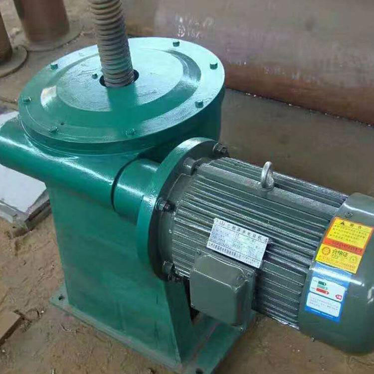
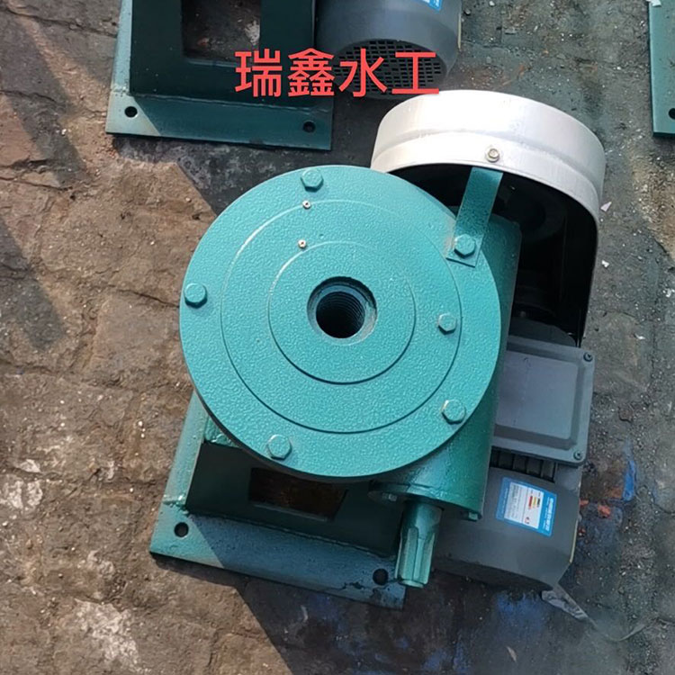
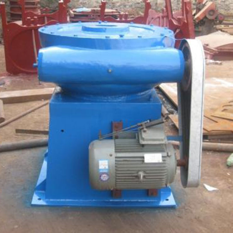
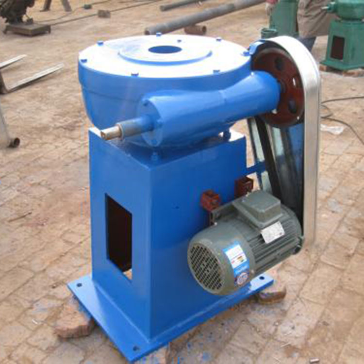
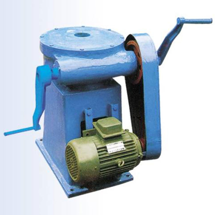
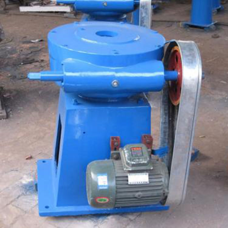
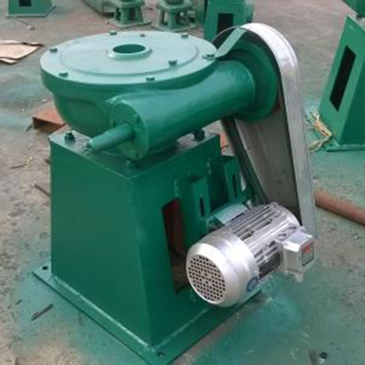
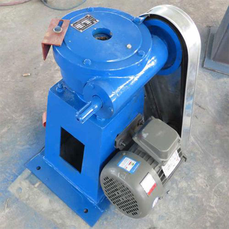
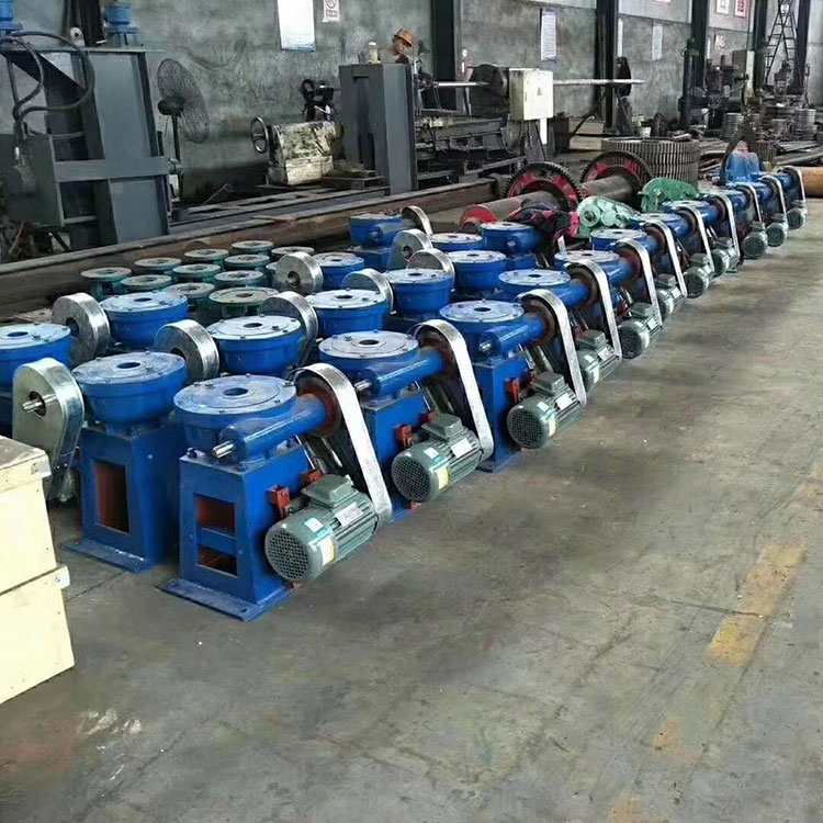
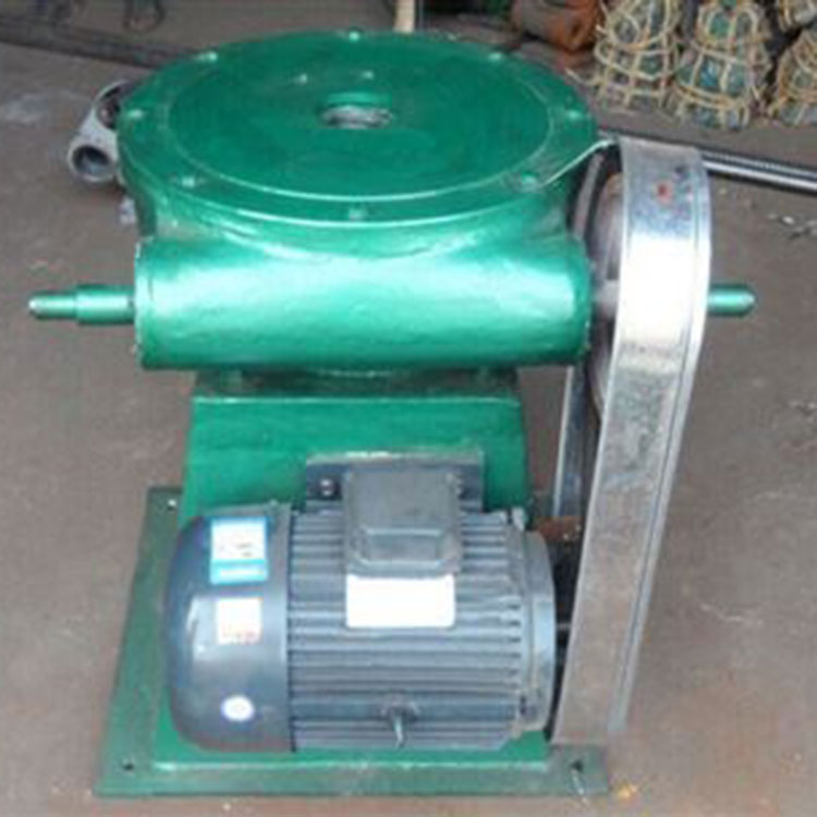
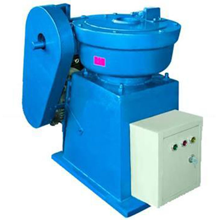
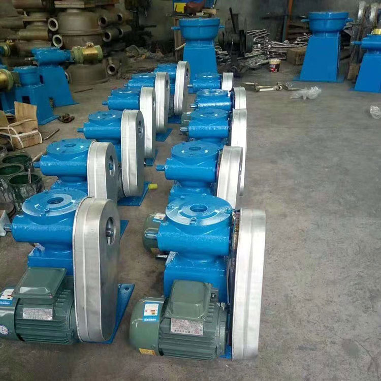
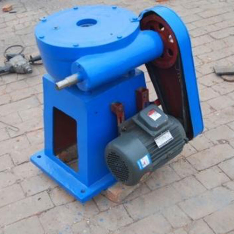
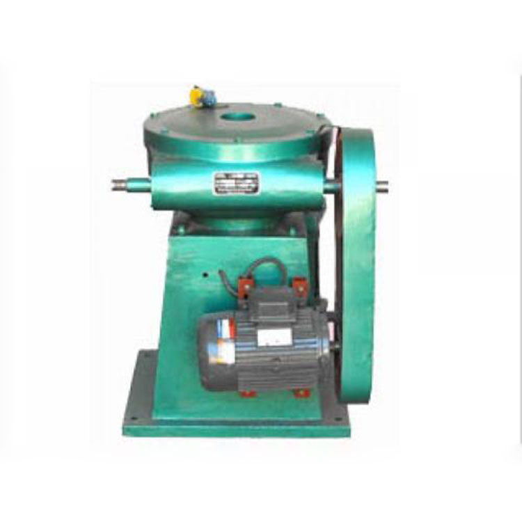
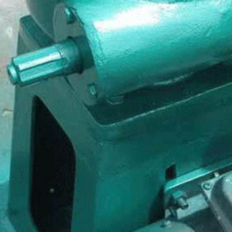
The twin-purpose hand-cranked screw gate operator, also known as the screw gate operator, is a mechanical device that directly or through gate hinge ears connects to the gate leaf with a threaded rod, moving the rod up and down to open or close the gate. The structure of the twin-purpose hand-cranked screw gate operator is extremely simple, and installation is also quite straightforward, widely used for gate operations in channel sluices and water intake structures. With the extensive development of water conservancy and hydropower projects, screw gate operators are extensively employed in reservoir irrigation areas, river embankments, and hydropower stations. The installation, commissioning, and maintenance knowledge for these operators should also be widely promoted. It is essential to普及 this technology and knowledge among construction and installation units, as well as management departments, to ensure the quality of construction and maximize the benefits of the projects.
Section 2: Installation of dual-purpose flashlight screw-type opening and closing machine
When installing the two-in-one hand-held screw-type gate opener, ensure the foundation layout is level at 180 degrees; the contact area between the base of the opener and the foundation layout should be over 90%; the screw axis must be perpendicular to the horizontal surface of the gate platform beam; it should align vertically with the hanging ears of the gate plate to prevent the screw from tilting, which could cause localized stress and damage the machinery.
After installing the two-in-one handlamp-style screw-type opening and closing machine, it is essential to conduct a trial run. First, perform a no-load test by allowing the screw to complete two strokes, listening for any abnormal sounds to check if the installation meets technical requirements. Second, conduct a load test by operating the screw through two strokes under the rated load, observing for any abnormal phenomena. Only after confirming there are no issues should the machine be operated officially. After running under load for a period, maintenance should be performed. Clean the new parts inside the machine, especially the screw, nut, turbine, and worm, gently and thoroughly, apply lubricating oil, seal them tightly, and continue use.
Section 3: Faults and Repairs of Dual-Function Handheld Screw Type Actuator and Shutoff Mechanism
1. Accidental top gate failure of the twin-handled screw jack due to non-human factors
During operation, floating debris such as trees or obstacles like rocks can be swept to the bottom of the gate or jammed in the gate slot by the high-speed water flow. If the gate is closed at this point, the lower edge of the gate is blocked by the obstacle before it touches the bottom, creating a reverse force. However, the limit indicator or limit switch on the screw hoist hasn't reached its position yet, and thus doesn't act as a limit stop or alert the operator to stop. Consequently, the operator may not stop the machine, and the hoist will continue to lower the gate. When the reverse force exceeds the load-bearing capacity of the hoist or the hoist platform, a gate jamming accident will inevitably occur. During use, particular attention should be paid to the gate jamming accidents associated with screw-type hoists. If such an accident occurs, it should be addressed promptly to prevent more severe incidents.
2. Human-induced gate failure incidents
Operators are negligent, failing to check the gate opening and closing procedures before operating, or a replacement operator, unfamiliar with the procedures, operates blindly. This may include reversing the opening and closing directions, such as opening the gate while it's in the closed position, pressing the wrong button on the electric operator, or reversing the direction manually; mistaking the closing direction for the opening one. In some cases, operators may be distracted during closing, failing to stop the machine in time when the gate reaches the lower limit position. Issues can also arise from the displacement of the screw rod's limiting nut or sign, rendering them ineffective. Electric operators may encounter power supply department maintenance work, causing changes in the power phase sequence, which alters the motor's original running direction, potentially changing the gate's opening and closing direction. If the gate is opened while in the closed position during such changes, a jamming accident is likely to occur.
IV. Causes of Screw Bending in the Dual-Use Screw Jack for Flashlights:
Gate opening indicator inaccurate or limit switch malfunction, causing the gate to continue closing after fully closed; incorrect operation of the power unit, causing a fully closed gate to continue closing; sudden jamming of the gate or obstruction by a stone or other obstacle on the bottom sill during closing; exceeding the allowable pressure of the screw due to violation of operating procedures; the length-to-diameter ratio of the screw and connecting rod of the hand-held two-way screw jack exceeds the allowable maximum or the guide arrangement spacing is too large; the installed screw and connecting rod errors are too large, causing jamming during closing. Repair methods: correction methods such as applying weights, levers, jacks, straighteners, presses, and heating can be used. After correction, the non-verticality should be controlled to: not more than 0.15mm per 0.5m length, not more than 0.7mm when the total length is not greater than 5m; not more than 1mm when the total length is 510m. If it exceeds the above standards, further correction is required.
To prevent further bending, the screw should be corrected and the cause of the bending addressed. This includes precisely adjusting the gate opening indicator, repairing and adjusting the limit switch, installing limit nuts, adjusting the safety coupling, modifying the screw and connecting rod's length-to-diameter ratio and guide points, and adjusting the screw's installation position.