


The screw compressor components in our screw air compressors are internally manufactured using a new CNC grinder, complemented by online laser technology, ensuring unparalleled manufacturing tolerances. Their reliability and performance guarantee that the operating costs of the compressor remain low throughout its service life. The new adjustments, integrated compressors, and desiccant series are all new products within the L/LS series compressors.
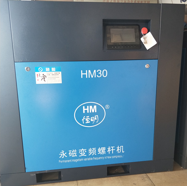
Screw air compressors provide compressed air for various industries with their advantages such as high efficiency, maintenance-free, and high reliability.

Advantages of Screw Air Compressors:
The screw air compressor equipment features high-capacity compression components with low peripheral rotor speed and oil injection, achieving efficiency and reliability. The new design ensures reduced system and compressed air temperatures. It guarantees that all components are cooled effectively and have extended service life.
1. Screw air compressors feature: high stability, high efficiency, low vibration, and low noise.
2. The yin-yang rotor and its fit with the housing are pre-set, resulting in minimal gas backflow leakage and no excess clearance volume, thereby ensuring high efficiency.
3. The lubricating oil injected has the functions of sealing, cooling, noise reduction, and lubrication.
4. Compared to piston engines, there are fewer wear parts and a lower failure rate.
5. The screw compressor's working curve is smooth, with less vibration compared to piston machines and lower noise levels.
6. Cooling methods generally include: water cooling and air cooling.
7. Heat Dissipation System: Utilizes a plate fin structure and materials, ensuring the cooler is pressure-resistant, high in heat dissipation efficiency, and good in corrosion resistance.
8. Air Filter: Heavy-duty, multi-stage air inlet filter with dust removal accuracy of 1um (98% removed), large working surface, and relatively long service life.
9. Oil/Gas Separator: The latest separator features new filter materials for enhanced efficiency, with oil content in air below 2ppm.
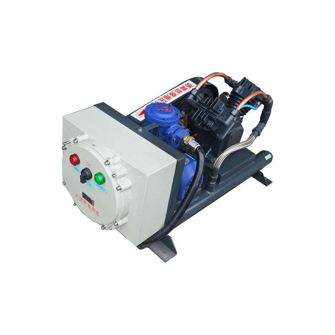
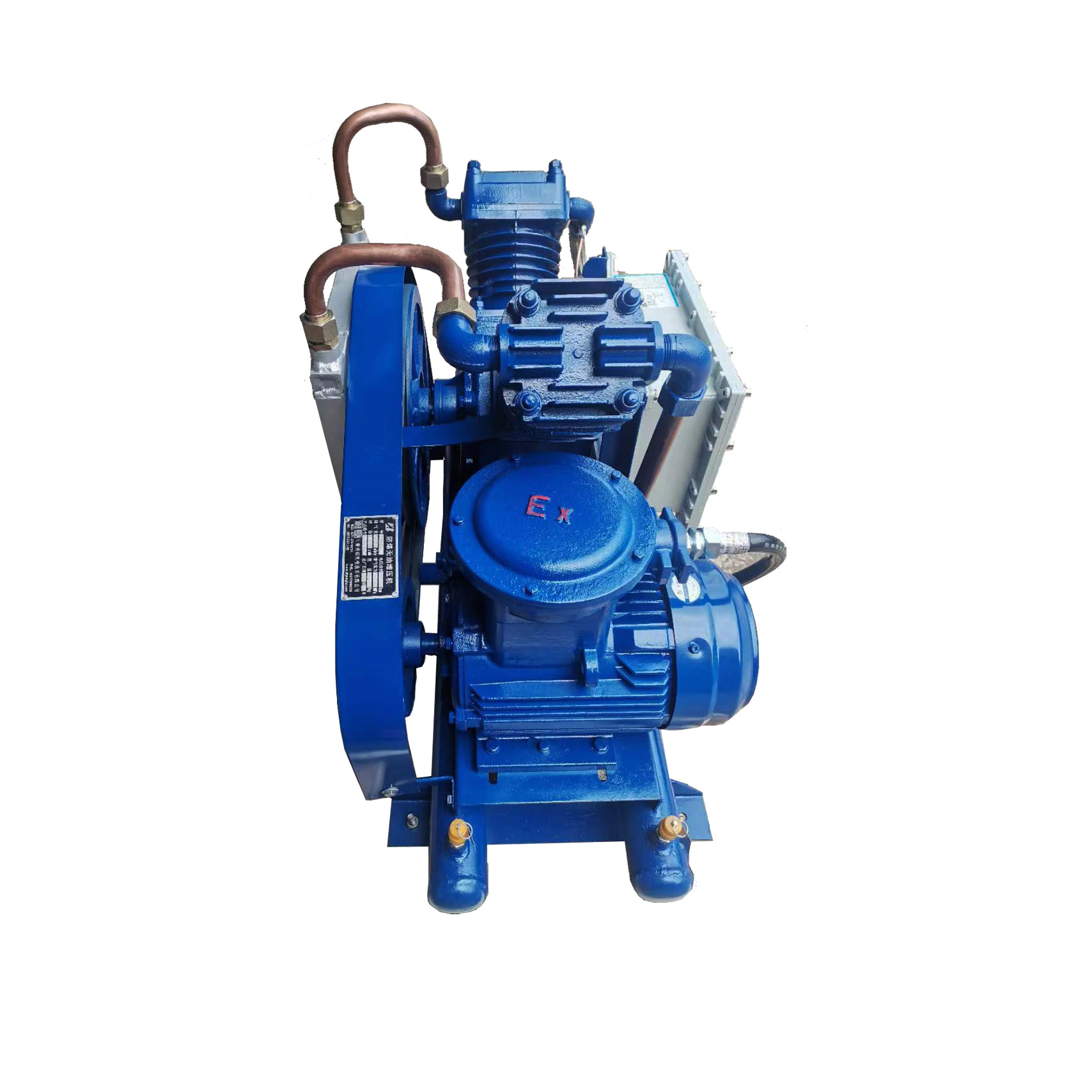
10. Smart Controller: All operations and relevant data of the air compressor are displayed on the control panel, allowing for easy and precise control at your fingertips.
Air Compressor Equipment - Screw air compressors are driven at speeds suitable for their application by the transmission system. No maintenance is required during normal operation.
Air Compressor Equipment - The innovative compressor design of our screw air compressors saves unnecessary maintenance costs. All components are designed for longevity, with large intake filters, oil filters, and fine separators ensuring compressed air quality. All oil filters and separator components for models up to 22kW (30hp) are centrifugal shut-off, further reducing maintenance time. The "Quick Repair Point" enables repairs to be completed in minutes, minimizing downtime and maintenance costs.
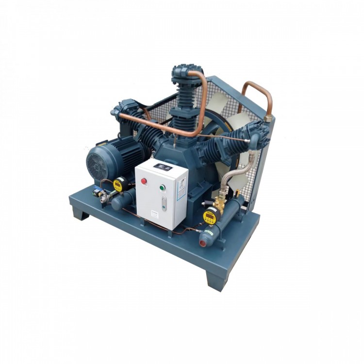
Screw air compressor principle:
(1) Suction Process: The motor drives the rotor. As the main and auxiliary rotors turn to the intake end wall opening, the space between their teeth is large, allowing external air to fill it. When the intake side face of the rotor moves away from the housing intake port, the air between the teeth is sealed between the main and auxiliary rotors and the housing, completing the suction process.
(2) Compression Process: At the end of the intake stroke, the enclosed volume formed by the main and auxiliary rotor tooth peaks and the housing decreases as the rotor angle changes and moves in a spiral manner, which is referred to as the "compression process."
(3) Compression Gas and Injection Process: During the conveying process, the volume continuously decreases, causing the gas to be compressed, increasing pressure and temperature. Simultaneously, due to the pressure difference, the lubricant in a mist form is injected into the compression chamber, achieving the effects of compression, temperature reduction, sealing, and lubrication.
(4) Exhaust Process: As the sealed tooth peak of the rotor rotates to meet the exhaust port of the housing, the compressed air begins to be released until the matching surface of the tooth peak and the groove reaches the exhaust end face. At this point, the groove space is zero, marking the completion of the exhaust process. Concurrently, another pair of grooves on the main and follower rotors have rotated to the intake end, creating a large space to start the intake process, initiating a new compression cycle.
Screw air compressor principle
Screw air compressor discharge volume:
Definition
Air volume discharged by the air compressor within a unit of time, converted to the suction state.
Factors affecting the actual exhaust volume of screw air compressors
Equipment RPM:
The discharge volume of a screw air compressor is proportional to its speed, which often varies with the voltage and frequency of the power grid. When the voltage or frequency decreases, the speed will drop, reducing the discharge volume of the screw air compressor.
2. Suction State:
Screw air compressors are volumetric compressors, maintaining a constant intake volume. When the intake temperature increases, or the intake pipeline has excessive resistance causing a drop in intake pressure, the gas density decreases, consequently reducing the screw air compressor's exhaust volume.
3. Gas Leak
There is no contact between the rotors and between the rotors and the housing during operation, maintaining a certain gap, which leads to gas leakage. When the gas, increased in pressure, leaks through the gaps into the suction pipe and the grooves that are currently suctioning, it reduces the exhaust volume. To minimize leakage, sealing teeth are provided at the top of the driven rotor's teeth, the driven rotor's root has sealing slots, and the end face is machined with annular or strip-shaped sealing teeth. If these sealing lines wear, it will increase the leakage amount, so these factors should be considered during routine maintenance.
4. Cooling Effect:
Gases heat up during compression, causing the temperature of the rotor and the casing to rise as well. As a result, the gas expands upon intake due to the heating from the rotor and casing, leading to a decrease in intake volume. Some screw air compressors incorporate oil cooling in their rotors, while the casings are cooled with water; one of the purposes is to lower the temperature. When the cooling is inefficient, temperatures rise, and the exhaust volume of the screw compressor decreases accordingly.
Screw air compressor operation and maintenance:
Safety Precautions
Operation, maintenance, and service of compressors must be performed by qualified personnel.
2. The compressor cannot be reversed. Before starting the compressor for the first time or after maintenance of the electrical control system, it is essential to first confirm that the motor's rotation direction matches the specified direction.
3. High-temperature components must be dismantled only after they have cooled to ambient temperature.
4. Recommend using screw compressor oil. Mixing lubricants of different brands is not permitted.
5. Do not make any modifications or additions to the compressor that affect its safety or reliability without the manufacturer's permission.
6. Original equipment manufacturer (OEM) components for compressors are specifically designed and manufactured. We recommend using genuine parts to ensure the reliability and safety of the compressor operation.
7. No blocking of the compressor intake during operation is permitted.
8. Compressed air is not to be used for breathing unless specifically marked as suitable for that purpose.
9. Compressors must not be operated under pressures or temperatures exceeding the specified limits.
10. Upon discovering any abnormal operation of the compressor, immediately shut down the compressor and promptly eliminate the anomaly.
11. Maintain and repair compressors with the correct tools.
12. Confirm all safety devices are re-installed and tools are removed from the compressor before starting up.
Maintain and service
Check oil levels, exhaust temperatures, and pressures daily; listen for any abnormal sounds.
2. Before starting up weekly, open the separator drain valve to discharge condensate water, check for any leaks, inspect the safety valve, and examine the belt wear (visual inspection).
3. Regularly inspect the intake control valve, low-pressure valve, electrical box connection terminals, safety valve, and cooling fan.
4. Regularly clean and sweep the cooler, test the reliability of the safety valve.
5. Regularly replace the oil filter element, oil separator filter element, intake filter element, and lubricating oil.
Common Troubleshooting
Machine not starting: Check the main switch and power cord, inspect the motor.
2. Machine doesn't load after power-on: Adjust the pressure switch setpoint or replace the pressure switch, check or replace the solenoid valve.
3. Compressor not unload, safety valve release: Adjust the pressure switch setpoint or replace the pressure switch, check or replace the solenoid valve.
4. Excessive Fuel Consumption: Follow recommended oil usage, lower fuel level to normal position, remove and clean return oil line, replace the fuel-oil separator filter element.
5. Excessive Exhaust Pressure: Reduce gas consumption or increase compressor capacity, check for system leaks, clean or replace the intake filter core, replace the oil-gas separator filter core, inspect or replace the solenoid valve, repair the intake control valve, replace the belt, adjust the pressure switch setpoint.
6. Compressor High Temperature Protection Shutdown: Improve environmental ventilation conditions, clean or wash the cooler, add oil to the designated position, replace the engine oil filter.
7. Compressor unloading operation, exhaust pressure still slowly rising, safety valve release: inspect or replace solenoid valve, repair intake control valve, repair unloading pipeline.
8. Safety Valve Discharge: Inspection or replacement of safety valves, maintenance of small pressure valves, replacement of oil-gas separator filter cores, inspection or replacement of pressure switches, check of intake control valve or solenoid valve.
Maintenance of the intake air filter core
The air filter is a component that filters out dust and impurities from the air, with the clean air then entering the screw rotor compression chamber for compression. Since the internal clearance of the screw compressor only allows particles of 15u or less to pass through, if the air filter element becomes clogged or damaged, a large number of particles larger than 15u will enter the compressor's internal circulation. This not only significantly shortens the service life of the oil filter element and the fine oil separator, but also causes a large number of particles to enter the bearing chamber directly, accelerating bearing wear, increasing the rotor clearance, reducing compression efficiency, and even causing the rotor to seize due to dry friction.
After 500 hours of operation, replace the oil filter element. Use a wrench to unscrew the oil filter element, install a new filter element by adding oil with a screwdriver, seal the filter element by hand-tightening the oil filter housing, and tighten it firmly. It is recommended to replace the new filter element every 1500-2000 hours, and replace the oil filter element at the same time as changing the oil. In harsh environments, the replacement cycle should be shortened. It is strictly prohibited to use the oil filter element beyond the expiration date, otherwise, due to severe clogging of the filter element, the pressure difference may exceed the bypass valve's tolerance limit, causing the bypass valve to automatically open, allowing a large amount of dirt and particles to enter the screw main engine directly with the oil, resulting in serious consequences. The replacement of the diesel screw compressor diesel engine oil filter element and diesel filter element should follow the diesel engine maintenance requirements, and the replacement method is similar to that of the screw oil filter element.
Separator maintenance and replacement
An oil-gas separator is a component that separates screw oil lubricant from compressed air. Under normal operation, the service life of an oil-gas separator is approximately 3,000 hours; however, the quality of the lubricant and the air filtration accuracy greatly affect its lifespan. It is evident that under harsh operating conditions, the maintenance and replacement cycle of the air filter core must be shortened, and even considering the installation of a pre-filter air cleaner. The oil-gas separator must be replaced when it expires or the pressure difference between the inlet and outlet exceeds 0.12 Mpa. Otherwise, it may cause motor overload and damage to the oil-gas separator, leading to oil leakage. Replacement method: Remove the control pipe fittings installed on the oil-gas drum cover. Take out the return oil pipe extending into the oil-gas drum from the oil-gas drum cover, and unscrew the bolts securing the oil-gas drum cover. Remove the oil-gas drum cover and extract the oil filter. Remove the asbestosis pad and debris stuck on the top cover plate. Install the new oil-gas separator, ensuring that the upper and lower asbestosis pads are nailed with staple pins and are properly aligned during tightening to prevent pad bursting. Reinstall the top cover plate, return oil pipe, and control pipes in their original positions, and check for any leaks.
Maintenance and Replacement
The quality of screw oil has a decisive impact on the performance of injection screw machines. Good oil products have excellent antioxidant stability, quick separation, good degassing properties, high viscosity, and good anti-corrosion performance, hence users must use genuine screw oil. The first oil change should be performed after the initial磨合 period of 500 hours, and then every 2000 hours of operation. Replace the oil filter at the same time as changing the oil. In harsh environments, shorten the replacement cycle. Replacement method: Start the air compressor and run for 5 minutes to raise the oil temperature above 50°C, reducing the oil viscosity. Stop the operation and, when the oil and gas drum contains 0.1 Mpa of pressure, open the oil drain valve at the bottom of the drum and connect to the storage tank. Open the drain valve slowly to prevent hot, pressurized lubricant from splashing and causing injury or contamination. Close the drain valve once the lubricant becomes drip-like. Unscrew the oil filter core and drain the lubricant from all pipelines simultaneously, replacing it with a new oil filter core. Open the oil filling cap, pour in new oil to ensure the oil level is within the oil level marking, tighten the cap, and check for any leaks. Regularly inspect the lubricant during use; if the oil level is too low, replenish with new oil promptly. Also, frequently drain condensate water from the lubricant, typically once a week, and more frequently in hot weather, every 2-3 days. After 4 hours of shutdown, open the drain valve when the oil and gas drum is pressure-free to expel condensate water, and quickly close the valve when oil starts to flow. Absolutely do not mix lubricants from different brands, and avoid using lubricant past its expiration date. Otherwise, the lubricant quality will degrade, leading to poor lubrication, lower flash point, and potential for machine shutdown due to high temperatures and spontaneous combustion of the oil.