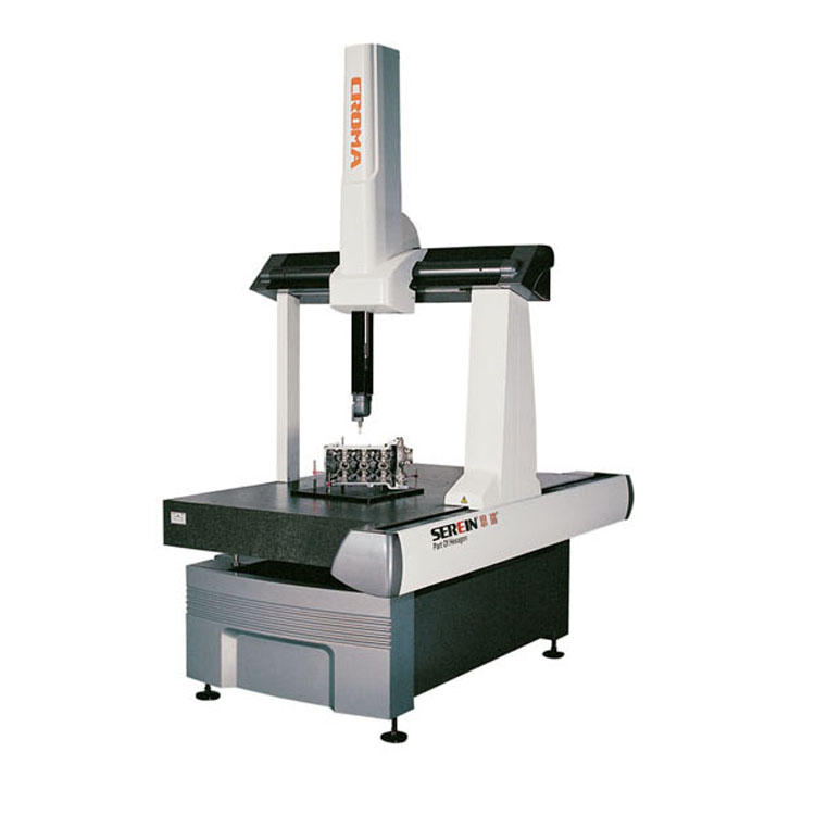

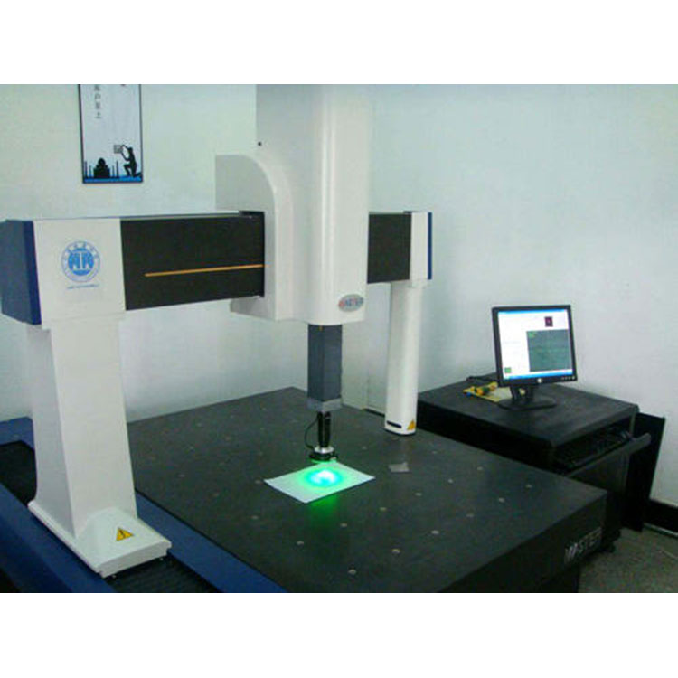


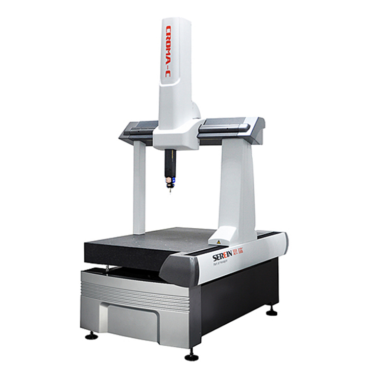


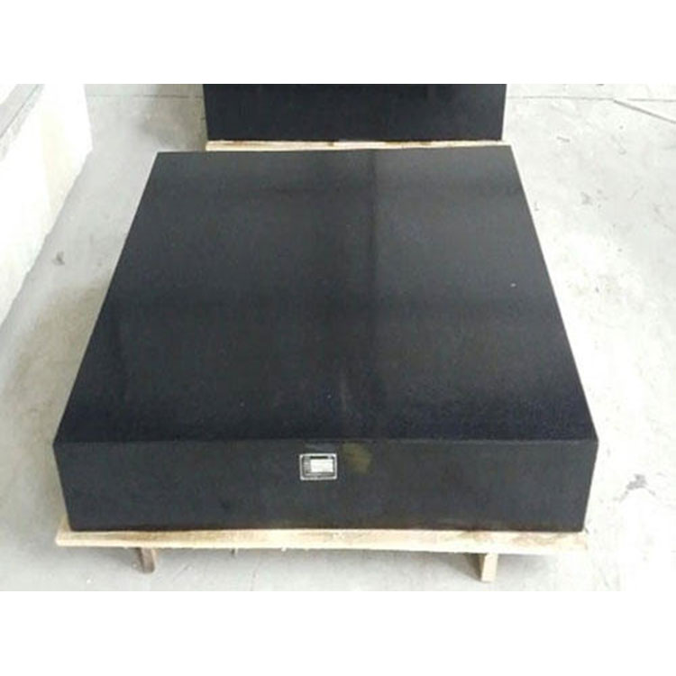
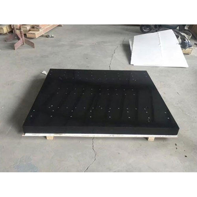
Three-axis measuring machine tables are used in three-axis measuring machines, also known as three-dimensional machines. These machines are instruments capable of measuring geometric shapes, lengths, and circumferential divisions within a hexahedral spatial range. They are also referred to as three-axis measuring instruments or coordinate measuring machines. A three-axis measuring machine can be defined as "an instrument equipped with a probe that can move in three directions, along three mutually perpendicular guides. The probe transmits signals through contact or non-contact methods, and the displacement measurement system of the three axes (such as an optical scale) calculates the coordinates (X, Y, Z) of each point on the workpiece and various functional measurements through a data processor or computer." The measurement functions of a three-axis measuring machine should include dimensional accuracy, positioning accuracy, geometric accuracy, and contour accuracy.
Original Working Quantity
Any shape is composed of points in three-dimensional space, and all geometric measurements can be reduced to the measurement of points in three-dimensional space. Therefore, the collection of spatial point coordinates is the foundation for evaluating any geometric shape.
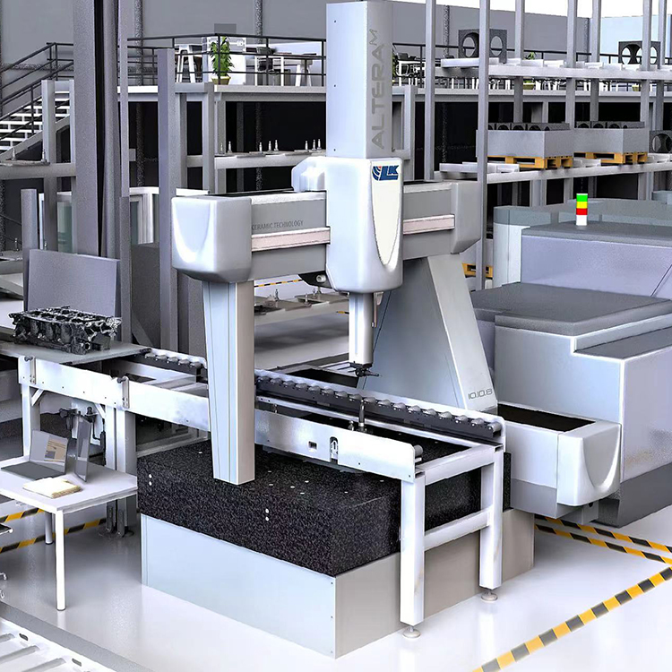
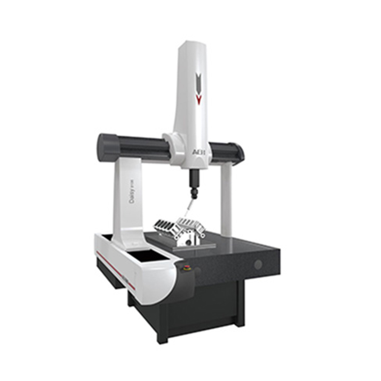
The fundamental principle of a coordinate measuring machine is to place the part to be measured within its allowable measurement space, then measure the points on the surface of the part at three coordinate positions in space. After computer processing of these points' coordinate values, they are fitted to form measurement elements such as circles, spheres, cylinders, cones, and surfaces. Mathematical calculations are then used to determine their shape, position tolerances, and other geometric data.
In the field of measurement, the advent of grating scales and subsequent capacitive, inductive, and laser interferometers has revolutionized the digitization of size information. Not only can they be displayed digitally, but they also lay the foundation for computer processing and control in geometric measurements.
A 3-axis measuring machine can be defined as "a probe that can move in three directions, capable of traveling along three mutually perpendicular guides, which transmits signals by contact or non-contact methods. The displacement measurement system of the three axes (such as an optical尺) calculates the coordinates (X, Y, Z) of each point on the workpiece and various functional measurements through a data processor or computer." The measuring functions of a 3-axis measuring machine should include dimensional accuracy measurement, positioning accuracy measurement, geometric accuracy measurement, and contour accuracy measurement, among others.
Basic Steps for 3-Axis Operation
1. Probe Calibration
Head probe calibration is a critical step in the three-coordinate measurement process for workpiece measurement on a 3D measuring machine. During the head calibration process, we select the appropriate probe and stylus based on the workpiece shape and dimensions. The majority of probes and styluses currently in use are Renishaw models, which are matched in the measurement software. Once selected, calibration is performed to achieve the required measurement accuracy.
2. Establish coordinate system
Establish the coordinate system for the workpiece. If a model of the workpiece is available, a model coordinate system should also be created, and then fit the workpiece coordinate system to the model coordinate system. The three elements for establishing a coordinate system are: first, determine a reference plane; second, determine a plane axis, such as the X-axis or Y-axis; third, determine a point as the origin of the coordinates.
3. Workpiece Measurement
Once the coordinate system is established, normal measurements can be conducted. The general steps for workpiece measurement are as follows:
Firstly, analyze the workpiece and measure the basic elements of the tool. Points, lines, surfaces, circles, cylinders, cones, etc.
Then, conduct shape tolerance analysis using basic elements based on the shape of the workpiece. Subsequently, output the inspection report as required.