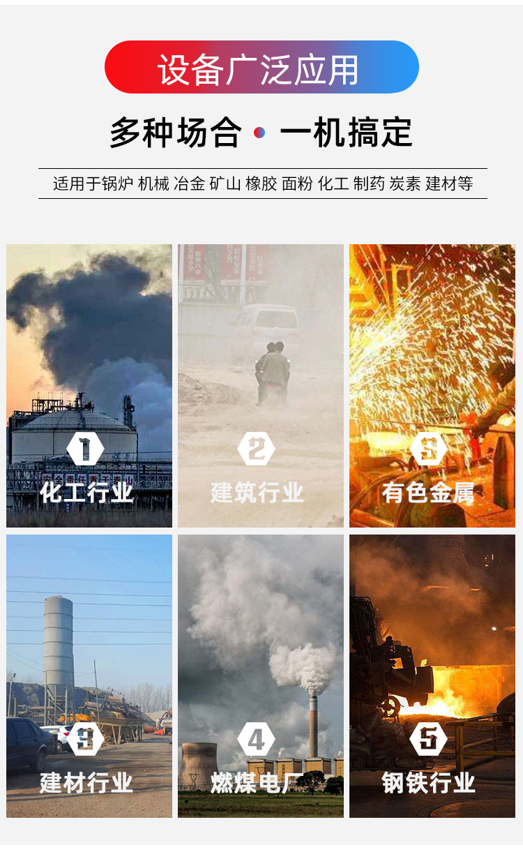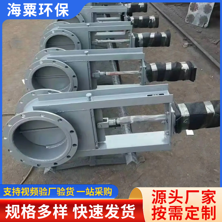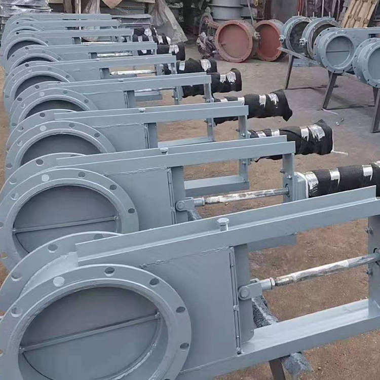


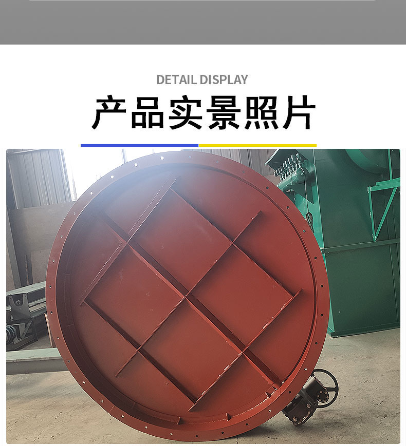
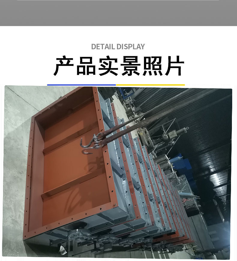
Air ventilation butterfly valves are used in ventilation and environmental protection projects in industries such as chemicals, building materials, power stations, and glass, within dust-laden cold or hot air gas pipelines, serving as pipeline control devices for regulating or cutting off gas flow. Such valves are generally installed horizontally within the pipeline.
Structural Features
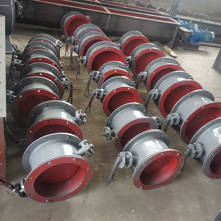
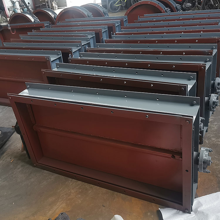
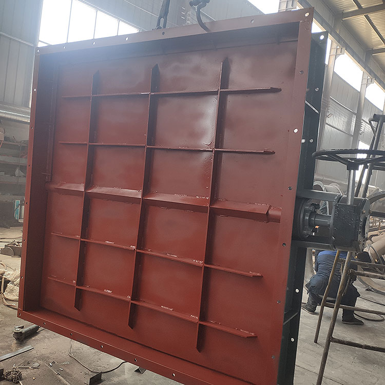
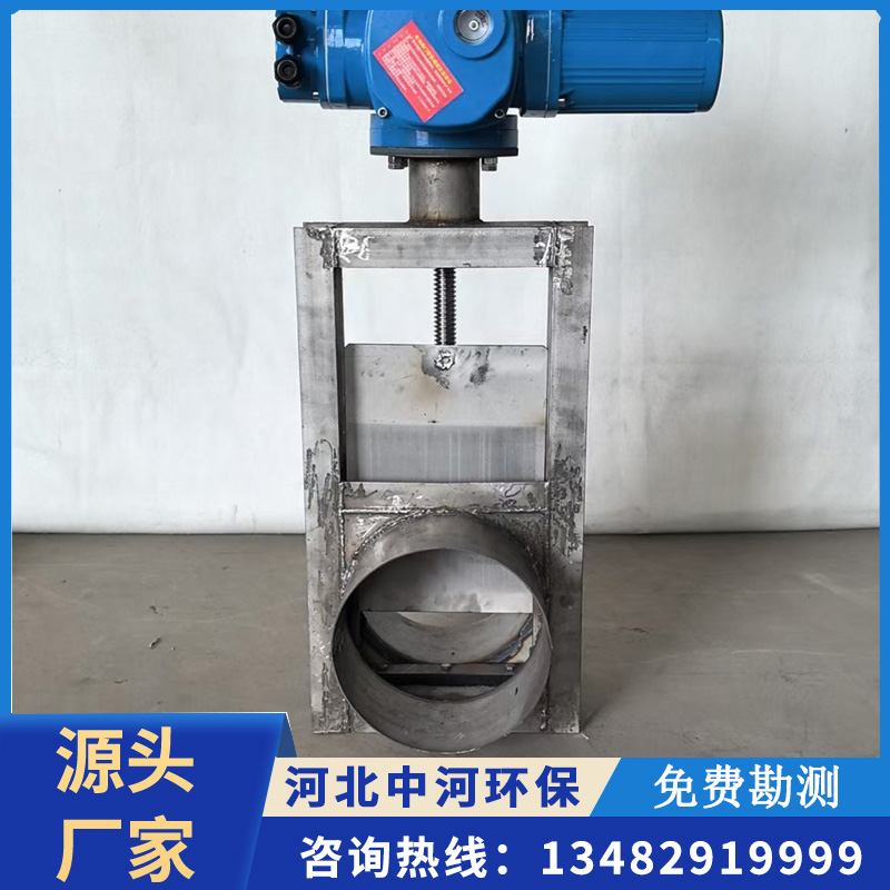
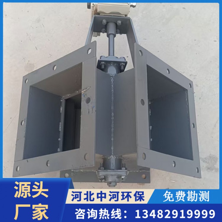
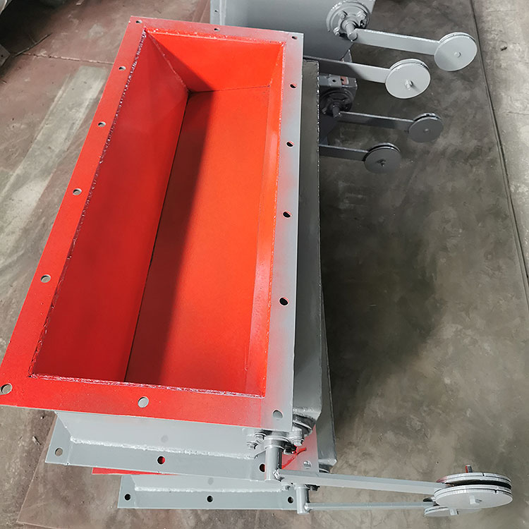
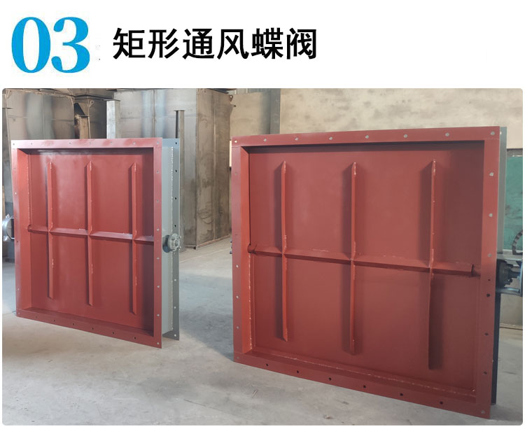
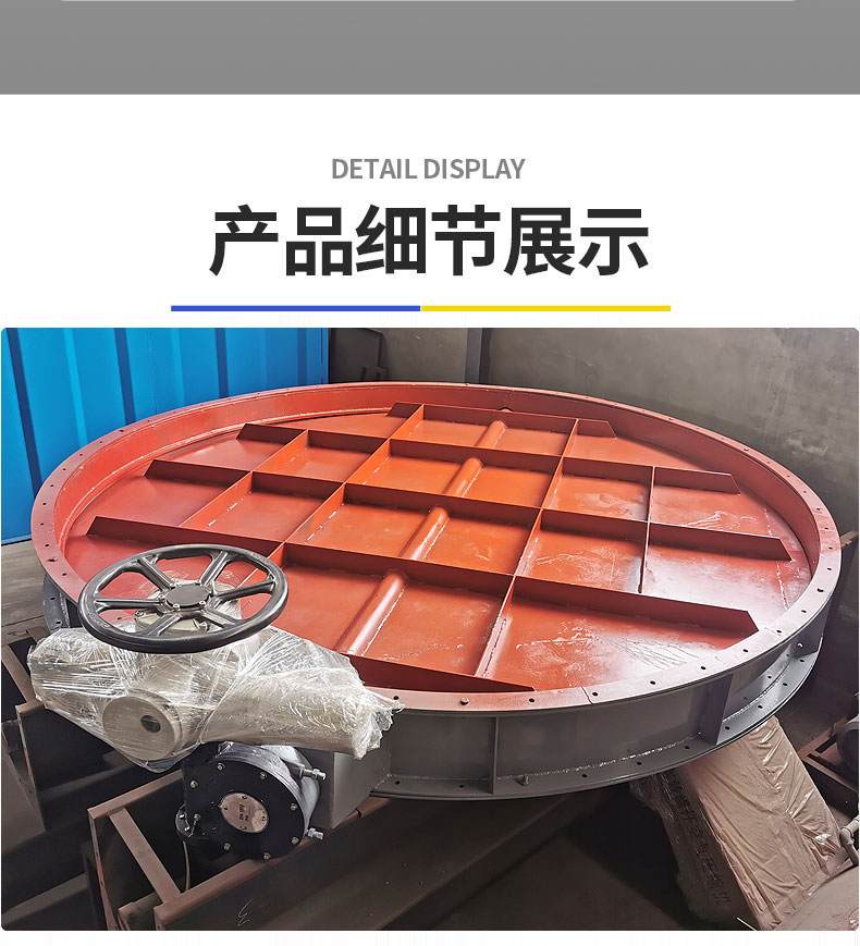
Manufactured with a new structural design featuring a mid-line butterfly plate welded to short structural steel plates, it boasts a compact structure, light weight, easy installation, low flow resistance, high flow capacity, and is unaffected by high-temperature expansion, with smooth operation.
2. Internally free of rods, bolts, etc., reliable operation, long service life. Can be installed in multiple stations without being affected by medium flow direction.
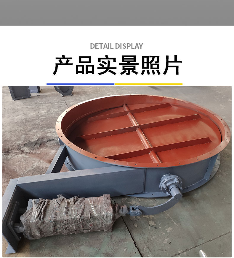
A ventilation butterfly valve is a non-sealed type of butterfly valve, widely used on pipelines with medium temperatures ≤300℃ and nominal pressure of 0.1Mpa in the production processes of building materials, metallurgy, mining, and power industries. It is used for connecting, opening, or adjusting the flow of the medium.
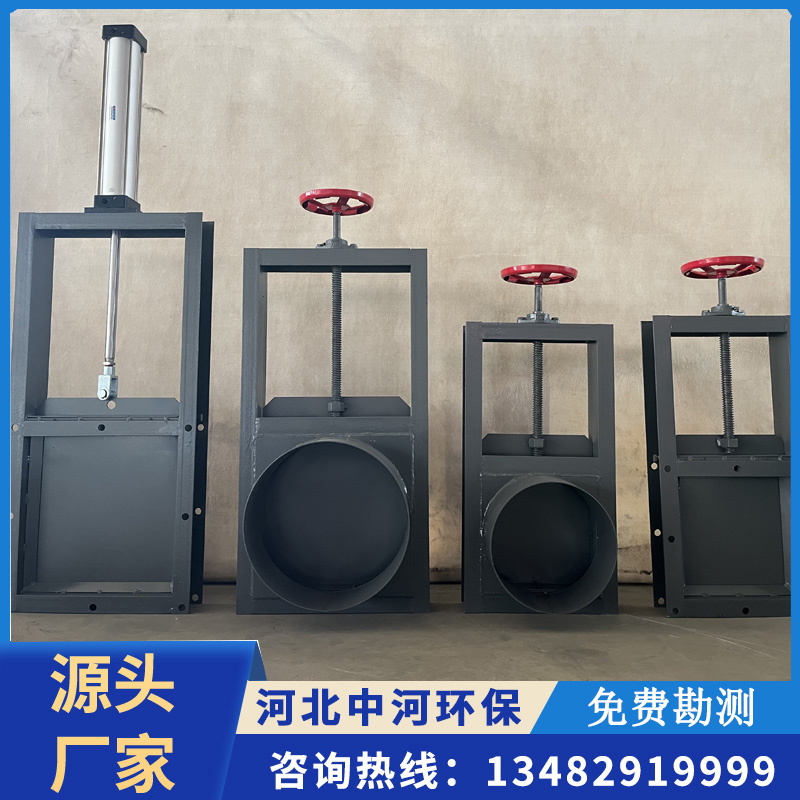
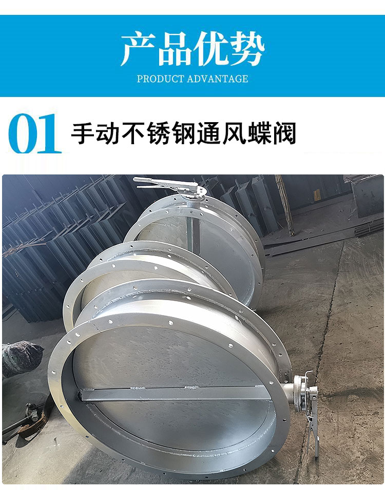
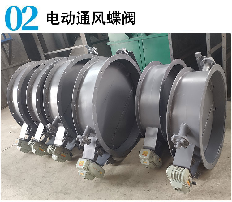
The butterfly valve is available in manual and electric drive types, powered by an electric motor or turbine to drive the actuator, allowing the butterfly plate to freely rotate within a 90° range for the purpose of opening, closing, or adjusting the flow rate of the medium.
Installation Points
The installation location, height, and进出口 direction meet design requirements. Pay attention that the direction of the medium flow should be consistent with the arrow direction on the valve body, and the connections should be secure and tight.
2. Prior to installation, perform an external inspection of the valve. The valve label must comply with the current national standard "General Valve Marking" GB 12220. For valves with working pressure exceeding 1.0 MPa and those acting as cutoff on the main trunk pipeline, a strength and tightness test must be conducted before installation. Only after passing the test can they be used. During the strength test, the test pressure should be 1.5 times the nominal pressure, lasting for at least 5 minutes, with no leakage from the valve body and stuffing as passing criteria. For the tightness test, the test pressure is 1.1 times the nominal pressure; the duration of the test should meet the requirements of GB 50243.