

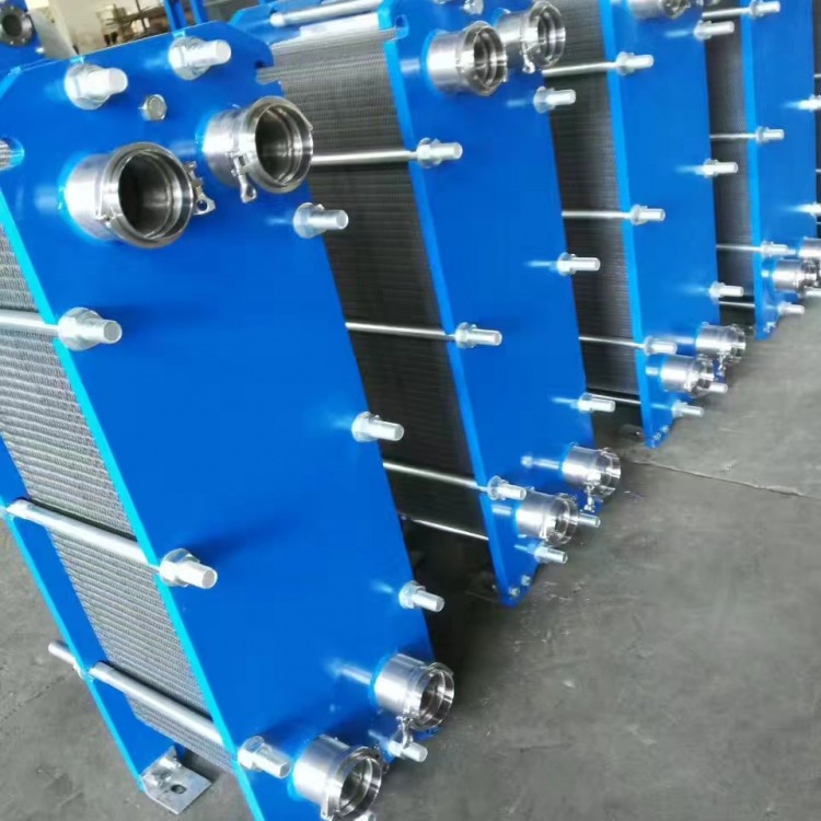

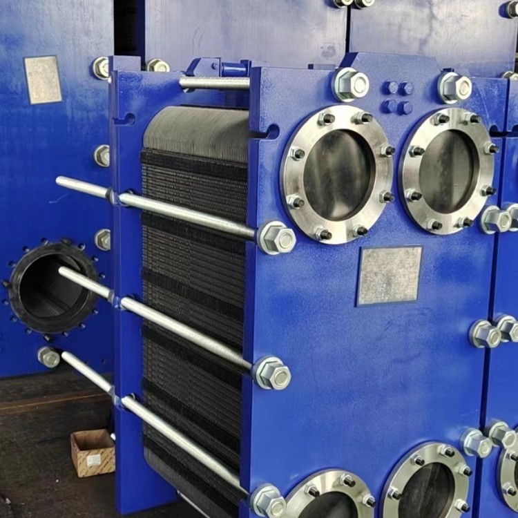
Shell-and-tube cooler, also known as a jacketed cooler, consists of a tube side and a shell side. The liquid flowing inside the tubes is the tube side, while the liquid flowing outside the tubes is the shell side. The wall of the tube bundle serves as the heat transfer surface. When the temperature difference between the tube bundle and the shell exceeds 50°C, appropriate temperature compensation measures are taken to eliminate or reduce thermal stress. Generally, it is water-cooled and holds a dominant position.
1. Tube-in-tube coolers utilize bare tubes (without finned surfaces) for heat transfer, featuring high heat transfer coefficients in the external tube wall and strong resistance to contamination.
2. The shell-and-tube coolers use purple copper tubes, which are machined into finned heat exchangers, resulting in a compact product size and a large heat exchange area.
3. Spiral flow baffles in the tube-type cooler ensure a continuous and uniform spiral movement of the cooled liquid, overcoming the heat exchange efficiency issues caused by the baffle plates in the baffled type.

4. Tube-in-tube coolers utilize胀管式封口,overcoming adverse changes that occur after high-temperature welding of materials.
5. Tube-in-tube coolers feature excellent structural performance, stable sealing, high heat transfer efficiency, compact structure, and minimal footprint.
Manual Process: After the filter is connected to the pipeline system, water enters from the lower inlet. As impurities in the water pass through the core, those with a larger volume than the core holes are trapped on the core. Once accumulated to a certain amount, it creates a pressure difference between the inlet and outlet. (The pressure difference varies with the filter mesh precision diameter, usually around 0.15 Mpa.) Manually open the drain valve to start the drainage process. Turn the handle, either clockwise or counterclockwise, turning one step every 10-30 seconds. The handle should be fixed at each indentation. The water reverses to wash away the impurities and dirt adhered to the inner wall surface of the core. Continue until a full rotation is completed, then close the drain valve to finish manual drainage.
As per customer selectionAutomatic Water FilterOptional differential pressure and timed discharge
1. Differential Pressure Backflushing: When impurities accumulate to a certain quantity, use the differential pressure signal between the cooling water inlet and outlet pipes for backflushing and draining. This means the electrical contact pressure gauge sends a control signal, which activates the control mechanism to open the electric drain valve. The electric reducer operates at a speed of 3-6 rotations per minute, reversing the flow of water to flush impurities adhering to the inner wall surface of the mesh core. The flushed debris is then drained through the drain pipeline and valve into the cooling water outlet pipe. Each cleaning and draining process takes approximately 5-10 minutes. In case of large debris that prevents the filter mesh from operating properly, the electric unit should run in the opposite direction to flush the debris.
2. Users may set the wastewater discharge timing as needed.0-99 hoursInternally set the cleaning and effluent discharge time, usually set to discharge once every 12 hours. The time setting can be adjusted according to the water quality of the power plant. That is, the electric reducer is set to reverse at the set time to open the effluent valve, followed by a reverse flushing and effluent discharge.
