
 Coiled Cable
 YR YRF Electric Hoist Cable Handle Line
 Flexible and Tug-Resistant CVC Cable
 H0FR Cable
 Polyurethane cable conduit
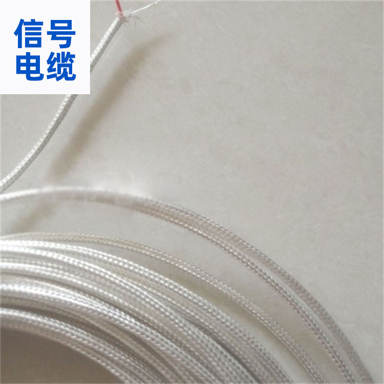 Signal Cable Manufacturer
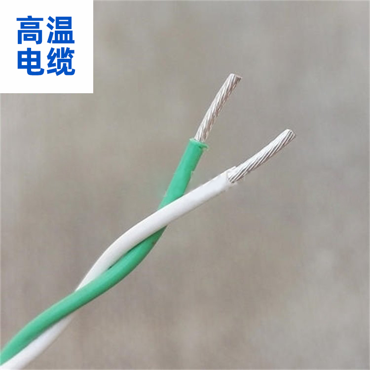 High-temperature cable
Product Details
Cables, wires, compensating wires, heating cables, instruments, meters, switc...

产品Price 5.50/Rice
最小起订Quantity:100 Rice 供货总Quantity: 999999 Rice


Color |
|
Core Count |
2 |
Temperature Range |
0-90°C |
Shield |
Copper wire, tin-plated copper wire |
Appearance |
Round |
Available for sale locations |
National |
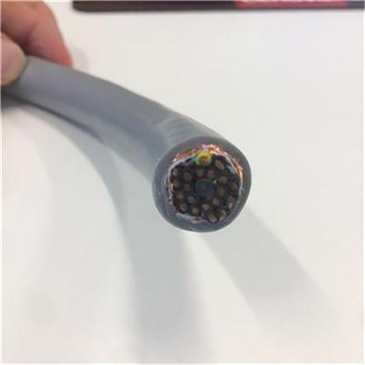
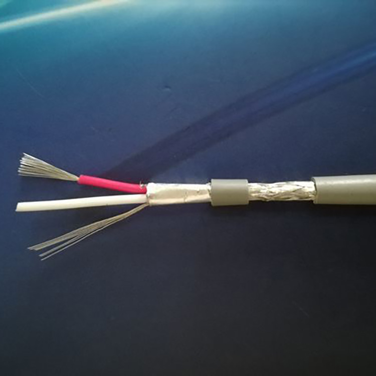
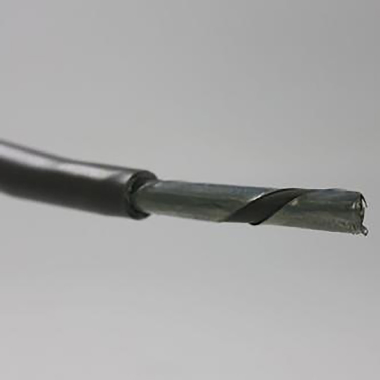
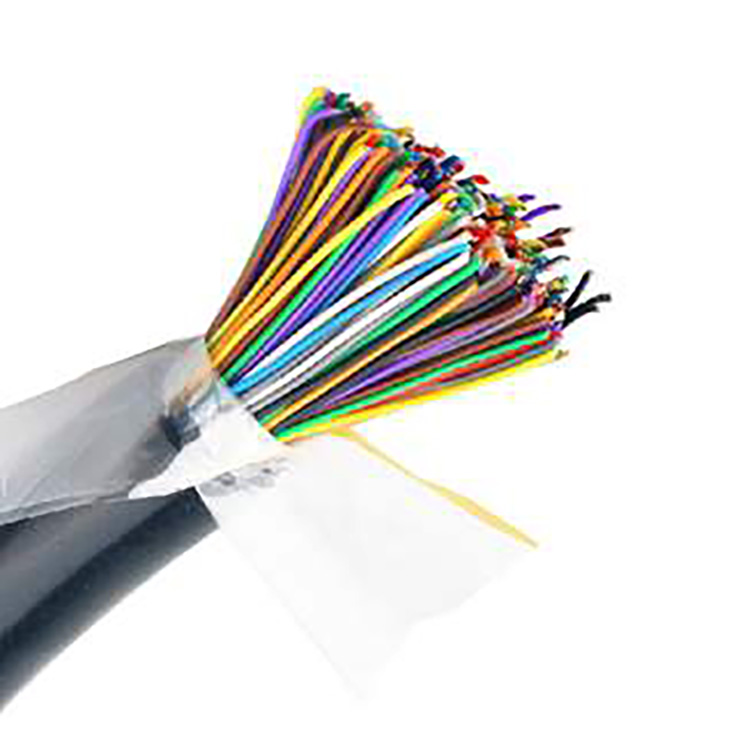
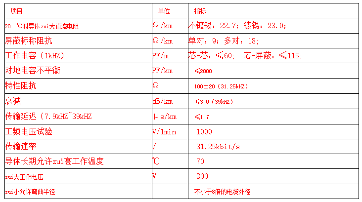
FF-A-1*2*18AWG Fieldbus Communication Cable FF-A-1*2*18AWG Fieldbus Communication Cable is suitable for connecting process automation control and measuring instruments in factory foundation control field environments, used to construct an open, decentralized digital fieldbus communication system. It is ideal for installation on cable trays (supports), inside pipelines, in both indoor and outdoor, humid or dry conditions. FF-A-1*2*18AWG Fieldbus Communication Cable Tin-plated Copper Core Soft Conductors 18AWG, Polyethylene Insulation, Red/Green Color, Double Shielding, Type A, FF Fieldbus Cable. The conductors of the FF-A type cable can also be made of soft copper wire, as per customer requirements. FF-A-1*2*18AWG Fieldbus Communication Cable Performance Parameters Table FF-A-1*2*18AWG Fieldbus Communication Cable experience shows that one of the main reasons for fieldbus loop failures is interference from the network segment, with the main cause of interference being poor installation of the fieldbus network segment and bus equipment. Installation experience includes: The fieldbus segment has high insulation requirements. To prevent explosion and moisture from entering the bus loop, explosion-proof junction boxes of increased safety type (EExe) are specified. When using explosion-proof cables, explosion-proof cable sealing joints should be used when cables are inserted into the junction box. Utilize FF bus-specific terminal blocks for connection with each bus field device. Each bus-specific terminal block features short-circuit protection, with an indicator light illuminating upon a short circuit. This ensures that a single branch short circuit does not affect the normal operation of other branches, as the short-circuit protector limits the short-circuit current per branch to no more than 60mA. ②Caution for cable shield layer connections. On fieldbus devices, the branch cable shield must be cut and insulated with insulating tape, and should not be connected to the grounding screw of the housing. The shields of each segment of the bus cable should be connected through grounding terminals within the junction box. The shields can only be grounded at the terminal on the cabinet side (marshalling). Good insulation from ground is required at any intermediate point, avoiding multiple grounding to prevent static induction and low-frequency (50Hz) interference. If the main cable is a multi-core cable, the shielded wires of different bus segments should not be interconnected within the junction box (JB) nor connected with the overall shielded wire. ③After the installation of fieldbus cables and field equipment, rigorous testing is required. The insulation resistance between cables, insulation to ground, capacitance between lines and to ground, and waveform testing of the bus signal should comply with the technical requirements of the FF Foundation's fieldbus system engineering guidelines. The connections of all terminals must be securely fastened. Section 2: Installation and Testing Methods for FF Fieldbus Fieldbus physical signals, terminals, power supplies, and inherent installations differ from conventional instruments; the cables used by both must be distinguished. The cable types, specifications, and maximum lengths for fieldbus cables available at 31.25kbps communication speed should be selected according to the project requirements. Generally, Type A is used for new installations; Type B can serve as a substitute; Types C and D are only used for modified installations. In engineering, attention must be paid to the shielding and grounding of cable lines, including A and B type shielded cables. C and D type cables can also be shielded by running the conductors through a metal tube and then connecting them together for grounding. The polarity issue between the cable line and the equipment must be noted; thus, the Manchester signals used in field buses are alternating voltages, with each bit speaking 1 or 2 times polarity. In non-powered networks, only this alternating voltage exists. In powered networks, alternating voltage is superimposed on the DC voltage supplying the equipment. In either case, the field bus receiving circuit only focuses on the alternating voltage. The transitions of positive and negative voltages represent different meanings, so the field bus signals are polarized. The power supply equipment for the bus is also polarized. It must be connected with the same polarity. Use color-coded cables for ease of construction. Currently, there are also non-polar devices for network power supply that can perform automatic polarity detection and correction, correctly receiving signals of different polarities, and can be connected blindly during use.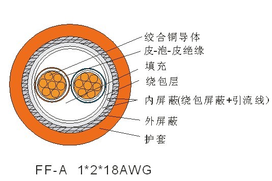

Phone Consultation