


CGM high-performance cementitious grout, steel structure grout, high-strength shrinkage-free grout, self-leveling grout, Shijia Guojian Manufacturer's main products:CGM High-Strength Non-Shrink Grouting Series, CGM-340, CGM-380, Epoxy Grouting, Epoxy Patching Mortar, CGM-320 Support Grouting, Fast-Filling Gravity Mortar, Setting Mortar, CGM High-Strength Emergency Repair Material; High-Strength Polymer Mortar, Epoxy Support Grouting, Polymer Crack-Resistant Mortar, Polymer Waterproof Mortar, Fast Repair Material for Cement Roadways, Track Mortar, Concrete Carbonation-Resistant Coating, Surface Treatment Agent, Prestressed Pipe Grouting Agent and Master Batch…
CGM High-Strength Non-Shrink Grouting Material
Product Features1. Early strength, high strength: compressive strength ≥27 MPa after 1 day; ≥40 MPa after 3 days; ≥60 MPa after 28 days.
2. Micro-expansive
Ensure tight contact between the equipment and foundation, with no shrinkage after secondary grouting.
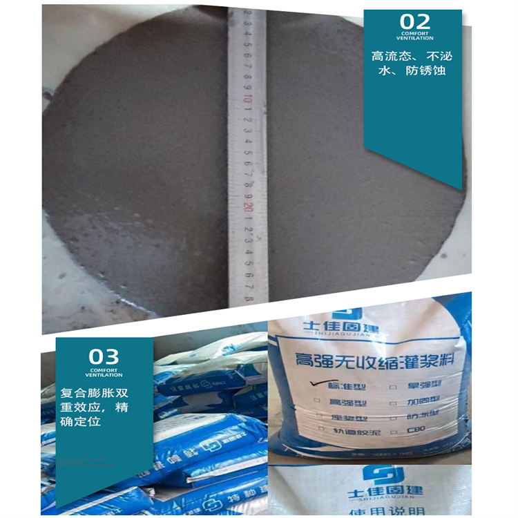
3. High self-leveling
Fills all voids, meeting the requirements for secondary grouting of equipment.
4. Anti-segregation
Overcame the segregation phenomenon caused by excessive water addition during on-site use.
5. Crack Resistance
Cracking phenomena during on-site use due to uncertain water addition, fluctuating environmental temperatures, and limitations on maintenance conditions.
6. Durable
After millions of fatigue tests50 freeze-thaw cycles showed no significant change in strength. After soaking in engine oil for 30 days, the strength increased notably.
7. Suitable for winter construction
Permitted toOutdoor construction at -10℃ temperatures.
Product Application:
Used for secondary grouting of equipment foundations.
2. For anchoring ground bolts and reinforcing bar embedding.
3. Used for reinforcing and repairing concrete structures.
Technical Specifications:
Pre-construction preparations
1. Mechanical Mixing: Concrete mixer or mortar mixer;
2. Manual Stirring: Several mixing tanks and shovels
3. Several buckets;
4. Several scales
5. Chute
6. High-position funnel, grouting pipes, and pipe connectors;
7. Grouting Propulsion Device
8. Templates (steel molds, wood molds)
9. Burlap bags, rock wool blankets, etc.
10. Cotton yarn, tape
Grouting construction
Step 1: Basic Processing
The base surface should be roughened. Clean the base surface, ensuring there are no debris, loose cement, dust, oil stains, and release agents, etc. Prior to grouting.24 hours, the base surface should be sufficiently moistened; before grouting, remove any standing water 1 hour in advance.
Step 2: Feel
1. Set up molds according to the grouting construction drawing. Seal the joints between the molds and the foundation, as well as between the molds themselves, with cement slurry and tape to ensure the integrity of the mold system is watertight.
2. The horizontal distance from the template to the base of the equipment should be maintained at approximately 100mm to facilitate grouting work.
3. The template top elevation should be 50mm higher than the surface of the equipment base.
4. In case of slurry leakage during grouting, it should be addressed promptly.
Step 3: Grout Mixture Preparation
Generally, water is mixed at a standard of 13-14% for general reinforced type, and 9-10% for pebble reinforced type.
2. Use mechanical stirring, which typically takes 1-2 minutes (handheld drills are strictly prohibited). For manual stirring, first mix with 2/3 of the water for 2 minutes, then add the remaining water and stir until uniform.
3. The mixing quantity should be determined based on the usage amount to ensure the material is used up within 40 minutes.
4. During on-site use, it is strictly prohibited to add any admixtures or external additives to the CGM grouting material.
Step 4: Grouting Construction Method
1. For longer equipment or track foundations, segmental construction should be employed.
2. Illustrations of Common Grouting Methods
3. During the secondary grouting, the following requirements should be met.
1.1 During secondary grouting, the grout should be applied from multiple points on one side or adjacent sides until it overflows from the opposite side, to facilitate air release during the grouting process. Grouting from all four sides simultaneously is not permitted.
1.2 Once grouting begins, it must be conducted continuously without interruption, and efforts should be made to minimize the grouting time.
1.3 No vibration is allowed during the grouting process. If necessary, the grouting material (cgm) can be propelled using a grouting booster along the bottom of the grouting layer. It is strictly prohibited to push from the middle or upper part of the grouting layer to ensure the uniformity of the grouting layer.
After the equipment base grouting is completed, a 45-degree bevel should be cut outward along the equipment edge within 3-6 hours after grouting (as shown in the figure below) to prevent cracks from forming at the ends. If edge cutting is not possible, the grouting layer surface should be smoothed with a trowel within 3-6 hours after grouting.
When the thickness of the grouting layer exceeds 150mm, use reinforced coarse aggregate high-strength shrinkage-free grouting material.
1.6 When the amount of base grouting for the equipment is large, mechanical mixing should be used for the gravel-reinforced grouting material to ensure the grouting construction.


