


- AllProduct Category
-
High-Pressure Igniter
Ignition Wires & Ignition Sticks
Three-Piece Ignition Unit / Seven-Piece Ignition Unit
Burner Tips & Torch Burners
Remote Electronic Ignition Device
Explosion-proof Ignition Detection Automation Control
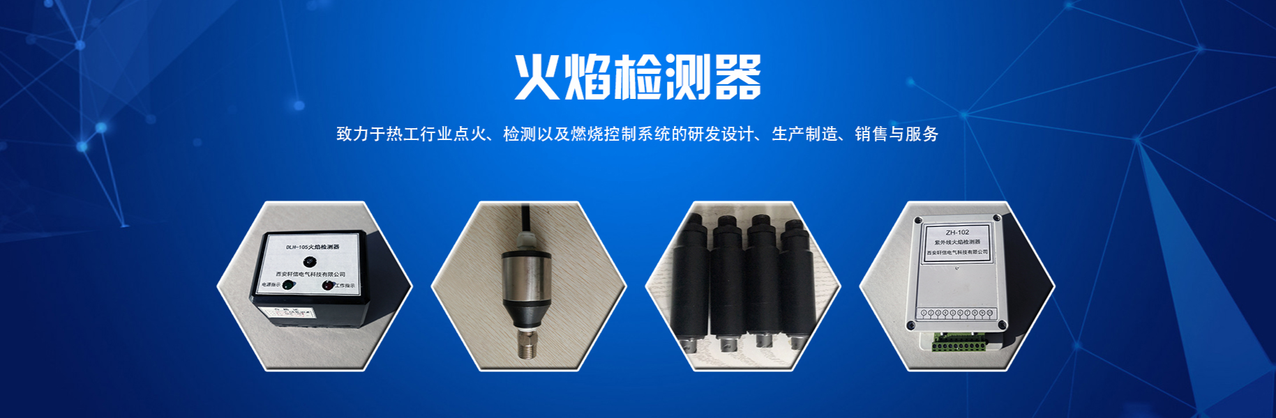
Flame Detector
Plasma Igniters
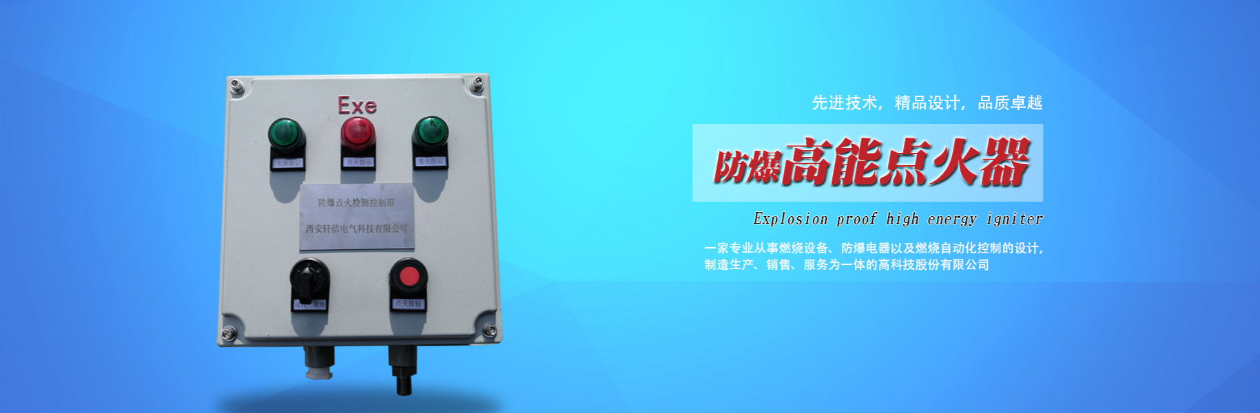
Explosion-Proof High-Energy Igniter
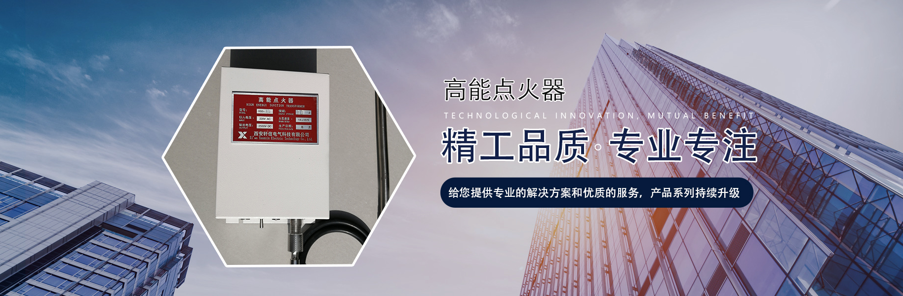
High-Energy Igniter


详情描述
Gas Well 7-Unit Ignition Device Instruction Manual
One,Product Description:
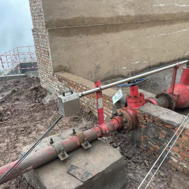
The seven-set gas well ignition device is primarily used in oil drilling operations for the combustion of flammable and harmful gases or waste gases during exploration and development, to eliminate their hazards to the environment and safety. It is a safe and environmentally friendly equipment.
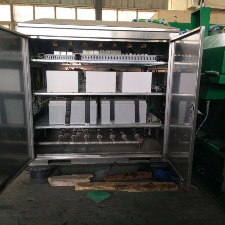
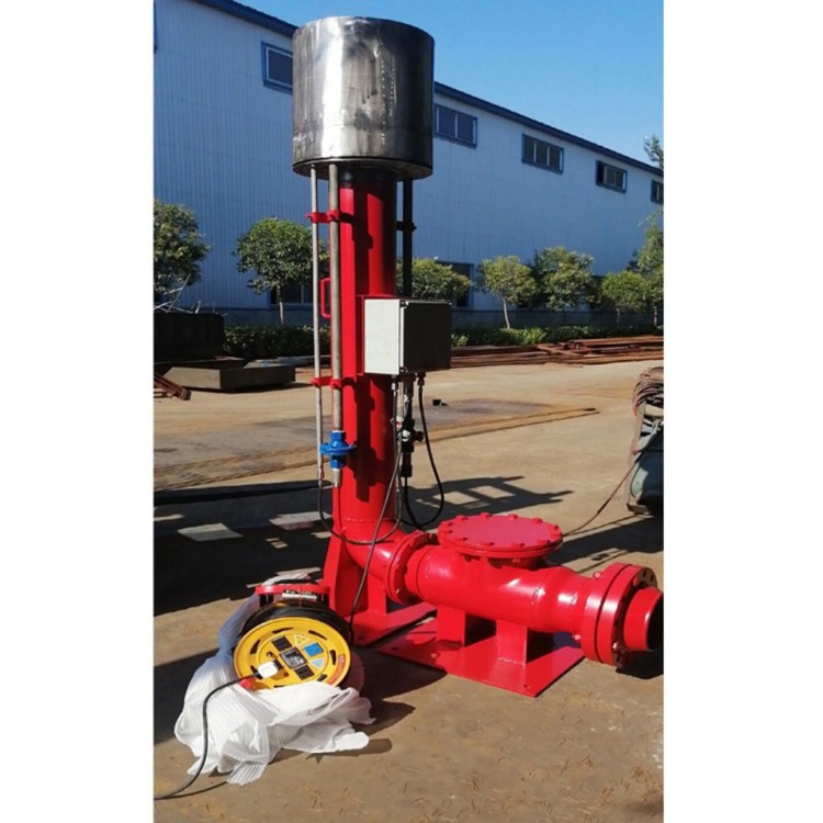
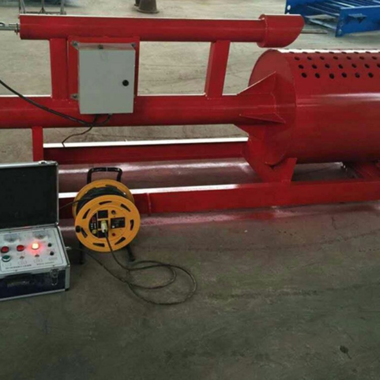
The seven-set gas well ignition device is mainly composed of a stainless steel control box, high-pressure connection lines, and ignition guns, among other components. The stainless steel control box is equipped with a 24VDC battery, which can be charged via an external 220VAC power source. Three sets of solar panels can also charge the battery. The ignition equipment is primarily operated through panel buttons. This product features a high-performance ignition circuit, ensuring stable performance and reliable operation.
The gas well seven-section ignition device ignition control box is also equipped with a real-time battery voltage monitoring circuit. When the battery voltage is too low, the under-voltage light on the operating panel illuminates and emits a buzzer alarm to remind users to charge promptly.
Section II: Technical Parameters of the Seven-Stage Ignition Device
1. Operating Voltage: DC 24V
2. External charging power supply; 220V
3. Environmental Temperature: -40~80℃
4. Charging Time: ≥8h
5. Lead-Acid Battery: 24VDC, 65Ah
6. Manual Ignition: Operated via manual buttons on the control box panel. Ignition duration is controlled by a timer relay (adjustable).
7. Dimensions: 1.2m (Height) * 1.0m (Length) * 0.7m (Width)
8. High-voltage Cable: L=80m/roll
9. Ignition Gun: (Length and外形 dimensions available for custom order according to customer requirements)
Length = 1000 + 115mm, Front-end temperature resistance 1300℃
Section 3: Technical Requirements for 7 Ignition Units
The seven-group ignition unit's overall performance is composed of one independent control cabinet, which internally controls seven ignition devices. Each control cabinet's main control section consists of seven individually independent ignition devices, capable of separately controlling the ignition of seven gas pipeline headers manually or remotely. The site can choose to use them based on actual needs. The specific requirements for the ignition devices of each control cabinet are as follows:
1. The ignition device should be capable of igniting the gas separated from the liquid-gas separator during the gas drilling and well-repair process, or the free gas discharged from the blowout line.
2. The ignition device should operate around the clock.
3. The equipment is powered by 3 independent power supplies, which can supply power to the ignition control section either individually or simultaneously. A 24V rechargeable battery should be used as a safe power source, accompanied by an automatic solar charging device. The solar charging/discharging controller must be placed inside the main electrical control box. In situations unfavorable for solar use, such as rain, snow, or fog, a 24V constant voltage power supply can be used on-site, connected to the power outlet in the main control box. The constant voltage power supply is one unit (DC24V, 500W) and must be placed inside the main electrical control box.
Each control cabinet features 7 control objects for ignition output control.
5. The ignition control system should display battery voltage parameters, be equipped with a power under-voltage indicator light, and have three voltmeters and three ammeters on the operating panel. It should show the voltage and current status of three sets of batteries.
6. Each ignition point (control object) should have an independent pilot gas.
7. Inside the control box, 7 ignition units are independently removable.
8. The air and electrical circuits are started with the same button, used for simultaneous start or stop.
4. Stainless Steel Box Panel Description:
There are 3 panel power switches, 3 battery power indicator lights, 3 charging indicator lights, and 3 low-voltage alarm lights.
3 voltmeters, 3 ammeters.
7 ventilation indicator lights, the corresponding ventilation indicator light illuminates when the solenoid valve is open.
7 ignition indicator lights, the corresponding indicator lights up when ignited.
7 start/stop buttons, for manual operation use start or stop
Stainless steel housing side mounting and a gas inlet
The cabinet features 7 gas outlets, 7 cable interfaces, 1 external power charging port, and 3 solar cable entry points.
V. Specific technical parameters of control cabinets and air lines
1. Lead-acid Battery: 24V DC × 65AH Maintenance-free Battery
2. Solar Panel Power: 3 sets x 50W per unit (12V), Dimensions: 550*670mm
3. Electromagnetic Valve: D15, installed inside the control cabinet.
4. High-voltage Cable: Armored Teflon, Ø2.5mm×80m, Protection ≤200℃
5. Constant Voltage Power Supply: 24V DC, 500W
6. Conductive Rod/Electrode: Pulse voltage ≥ 2500V, temperature resistance ≤ 1200°C, electrical spark energy 20 joules


