
 LDB Integrated Electromagnetic Flow Meter
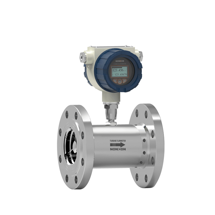
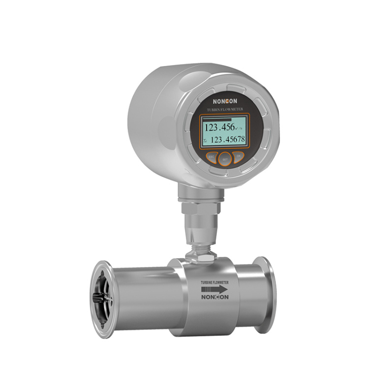 LWGS Food Hygiene Turbine Flow Meter
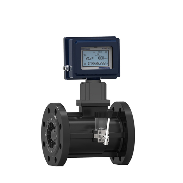 LWGQ Series Gas Turbine Flow Meters
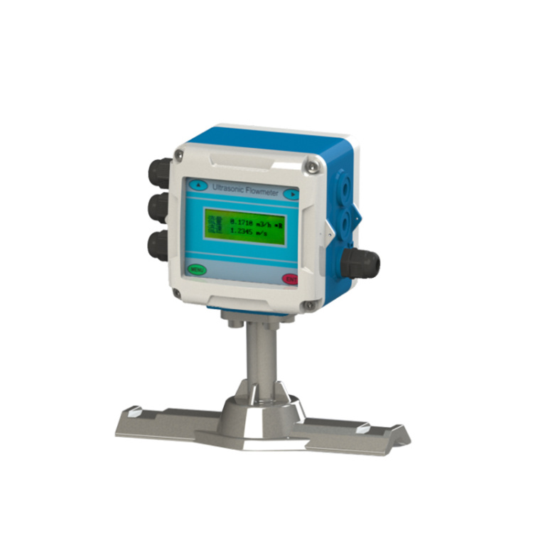 Fixed ultrasonic flowmeter
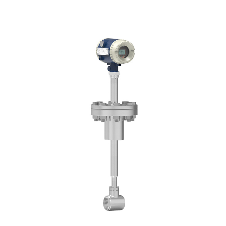 LUGC Insertable Vortex Flow Meter
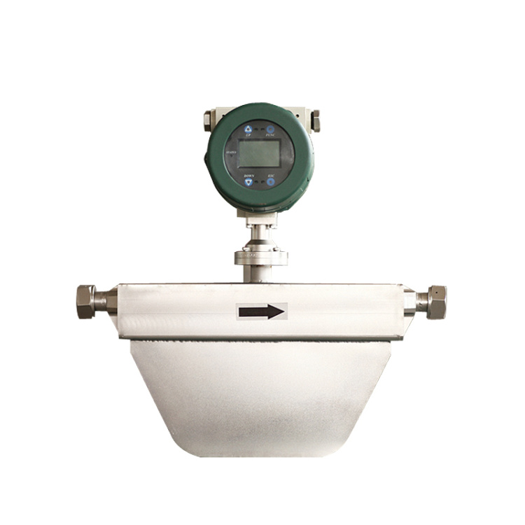 Liquid Mass Flow Meter
 LF Series Liquid Mass Flow Meters
Product Details


产品Price Negotiable
最小起订Quantity: 供货总Quantity:


Do we offer customization? |
|
Specs |
Comprehensive |
Shipment Time |
As per product specifications |
Ⅰ. Product Features Section IV: Product Classification Description As per different installation methods The installation method of the sensor varies by specification, utilizing either threaded or flanged connections. The installation methods are illustrated in Figures 4, 5, and 6, while the installation dimensions are listed in Table 4.
High precision, typically up to ±1%R, ±0.5%R for general models, and up to ±0.2%R for high-precision models.
■ Good repeatability, short-term repeatability up to 0.05%~0.2%. Due to its excellent repeatability, high accuracy can be achieved through regular or online calibration, making it a preferred flowmeter for trade settlement.
■Output pulse frequency signal, suitable for total quantity measurement and computer connection, with no zero-point drift and strong anti-interference capability.
High-frequency signals (3~4kHz) available with strong signal resolution.
Wide range, medium to large bore up to 1:20, small bore at 1:10.
■ Compact and lightweight structure, easy to install and maintain, with high flow capacity;
■ Suitable for high-pressure measurement; no need to drill holes in the instrument body, easily made into a high-pressure model gauge.
We offer a wide variety of sensor types, which can be customized to meet specific user requirements, including low-temperature models, bidirectional, downhole, and sand-mixed sensors, among others.
■ Available in insertable style, suitable for large diameter measurements, with minimal pressure loss, low cost, continuous flow extraction capability, and easy installation and maintenance.
II. Structural Features and Working Principle
Structural Features
The sensor features a hard alloy thrust bearing, ensuring precision, enhanced wear resistance, and boasts features such as simple structure, durability, and easy assembly and disassembly.
(2) Working Principle
Fluid flows through the sensor housing. Due to the angle between the blades of the impeller and the flow direction, the fluid's thrust imparts a torque to the blades, causing them to rotate. After overcoming the frictional torque and fluid resistance, the blades spin, and once the torque is balanced, the speed stabilizes. Under certain conditions, the speed is proportional to the flow rate. Because the blades are magnetically conductive, they are within the magnetic field of the signal detector (comprised of a permanent magnet and a coil). As the blades rotate, they cut through the magnetic lines, periodically altering the magnetic flux through the coil, which in turn induces an electrical pulse signal at the ends of the coil. This signal is amplified and shaped by an amplifier to form a continuous rectangular pulse wave of a certain amplitude, which can be transmitted remotely to a display instrument, showing the instantaneous or total flow rate of the fluid. Within a certain flow rate range, the pulse frequency f is proportional to the instantaneous flow rate Q through the sensor. The flow equation is:
Q=f/k*3600
In the formula:
Pulse Frequency [Hz]
k---- Instrument coefficient of the sensor [1/m³], provided by the calibration sheet.
The仪表系数 for each sensor is filled in by the manufacturer on the calibration certificate. Inputting the k value into the matching display meter allows for the display of instantaneous flow rate and total cumulative volume.
III. Instrument Classification
1. Categorized by instrument function, the LWGY series turbine flowmeters can be divided into two main categories: (1) Turbine Flow Sensor/Transmitter (2) Intelligent Display Turbine Flowmeter:
Turbine Flow Sensor/Transmitter
This type of turbine flow product does not have on-site display capabilities; it only transmits flow signals remotely. The flow signals can be pulse signals or current signals (4-20mA). The instruments are cost-effective, highly integrated, and compact in size, making them particularly suitable for use with secondary display instruments, PLCs, DCSs, and other computer control systems.
The product can be categorized into LWGY-N type and LWGY-A type based on different output signals.
LWGY-N type sensor: 24VDC power supply, three-wire pulse output, high level ≥8V, low level ≤0.8V; signal transmission distance ≤1000 meters.
LWGY-A Type Transmitter: 24VDC power supply, 2-wire 4-20mA output, signal transmission distance ≤1000.
These turbine flow products are divided into two types: the basic model and the explosion-proof model (ExdIICT6), as shown in Figures 1 and 2.
(2) Smart Display Turbine Flow Meters
The newly developed intelligent instrument with a turbo flow sensor and integrated display, designed using advanced ultra-low power single-chip microcomputer technology, features dual-row LCD local display. It boasts of its compact structure, intuitive and clear readings, high reliability, immunity to external power interference, lightning resistance, and cost-effectiveness. The instrument has three-point correction for instrument coefficients, intelligent compensation for non-linear instrument coefficients, and on-site correction capabilities. The high-definition LCD display simultaneously shows instantaneous flow and cumulative flow, with a zeroing function. All valid data is retained for 10 years even after power failure. This type of turbo flow meter is a explosion-proof product.
Protection Class: ExdIICT6.
These types of turbine flow meters are categorized into LWGY-B and LWGY-C models based on their power supply method and whether they have remote signal output capabilities.
LWGY-¨B Type: Powered by a 3.6V/10Ah lithium battery (capable of continuous operation for over 3 years).
LWGY-¨C Type: Supplied with a 24VDC external power source, it outputs a standard 4-20mA two-wire current signal. Optional HART communication or RS485 communication can be added based on different site requirements.

2. By different signal detector types
V. Selection Instructions
VI. Installation Dimensions


Phone Consultation