
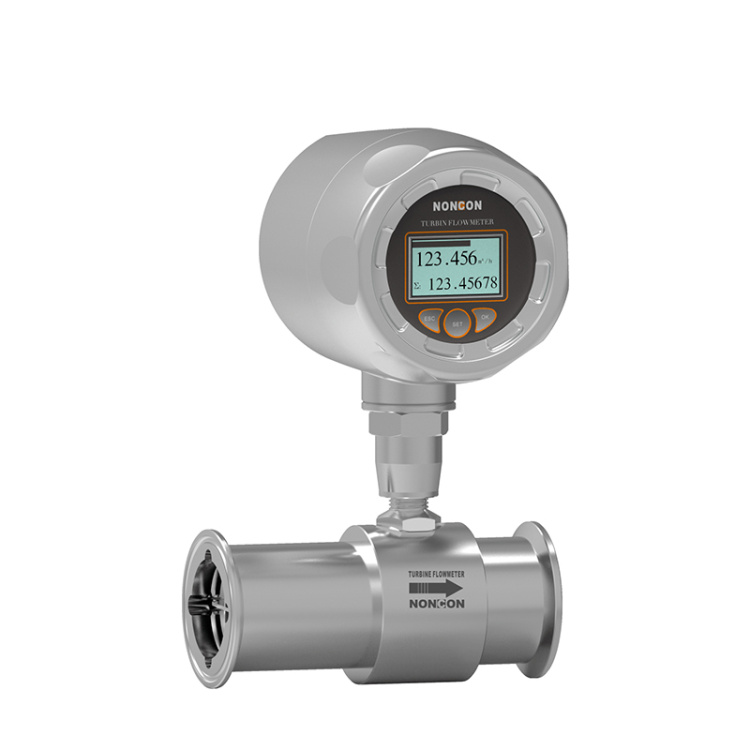
 LWGS Food Hygiene Turbine Flow Meter
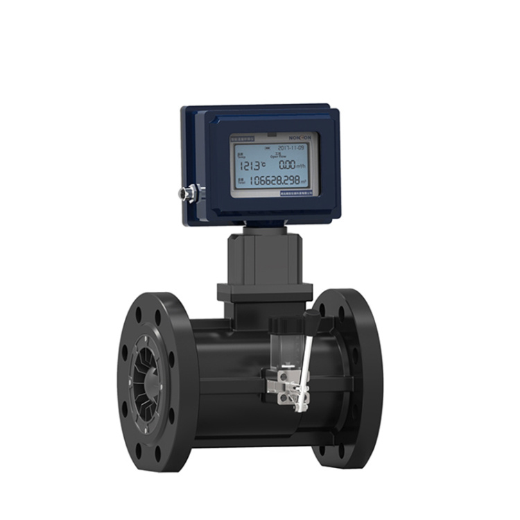 LWGQ Series Gas Turbine Flow Meters
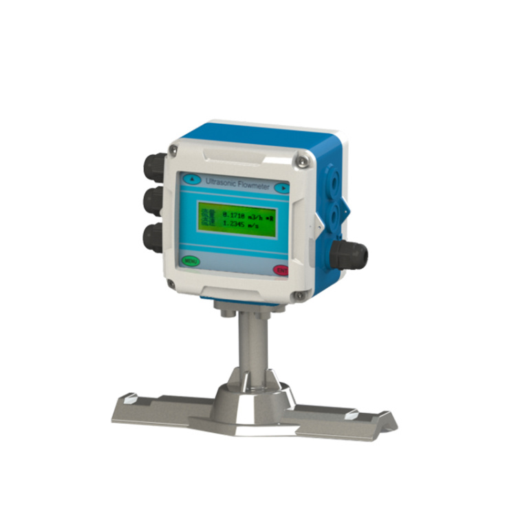 Fixed ultrasonic flowmeter
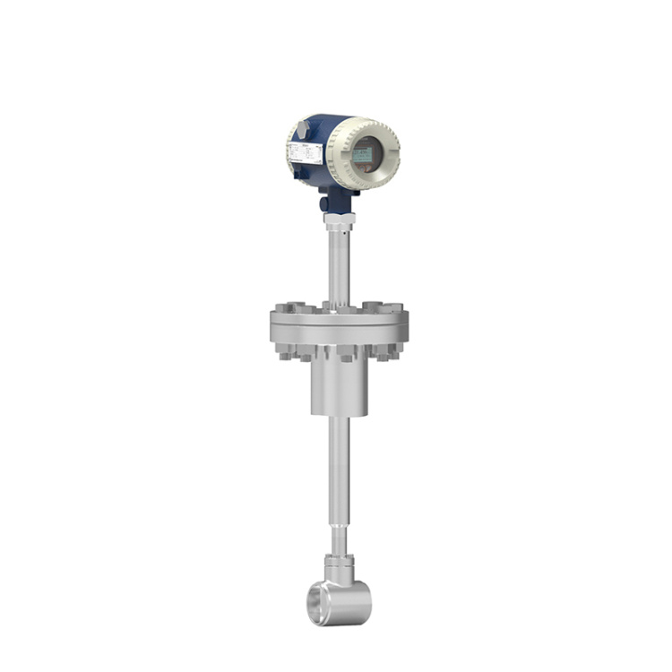 LUGC Insertable Vortex Flow Meter
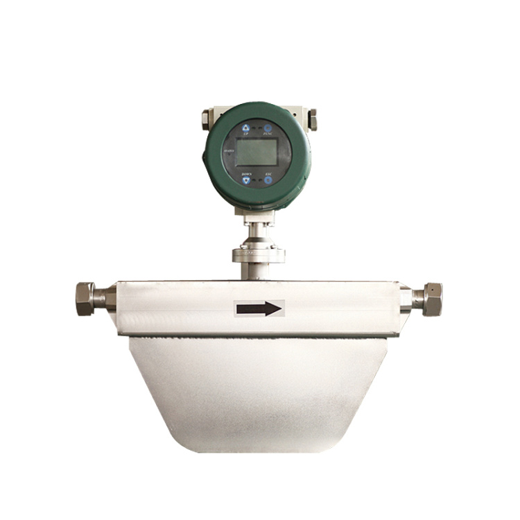 Liquid Mass Flow Meter
 LF Series Liquid Mass Flow Meters
Product Details


产品Price Negotiable
最小起订Quantity: 供货总Quantity:


Do you offer customization? |
|
Specs |
Complete |
Shipment Time |
As per product requirements |
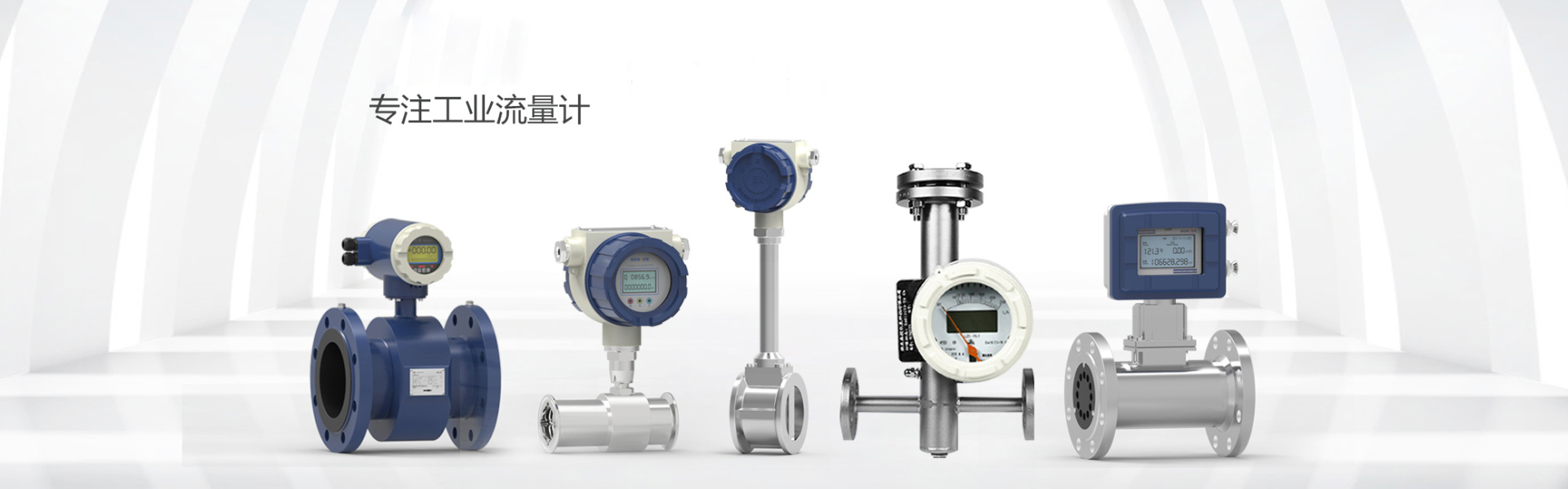
Product Features Product Selection
All-digital processing, strong anti-interference capability, reliable measurement, high accuracy, flow measurement range up to 150:1.
Ultra-low EMI switching power supply, suitable for a wide range of power voltage changes, and excellent EMI resistance.
■ Featuring a 16-bit embedded microprocessor, offering fast computation speed, high accuracy, programmable low-frequency rectangular wave excitation, which enhances the stability of flow measurement and low power consumption.
■ Utilizing SMD components and surface mount technology (SMT), the circuit boasts high reliability.
The pipeline contains no moving parts, no flow restrictive components, and experiences minimal additional pressure loss during measurement.
■On-site, the range can be modified online according to the user's actual needs.
The measurement results are unrelated to flow distribution, fluid pressure, temperature, density, viscosity, and other physical parameters.
High-definition backlit LCD display, full Chinese menu operation, easy to use, simple and intuitive to operate and learn.
■ Featuring digital communication signal outputs such as RS485, RS232, Hart, and Modbus (optional);
Self-check and self-diagnostic functions available.
Hourly Total Volume Recording Function, records total flow volume on an hourly basis, suitable for time-of-use metering (optional);
The unit features three calculators to independently display positive cumulative, negative cumulative, and differential cumulative quantities. It is equipped with a non-volatile clock that can record up to 16 power failure times (optional).
Infrared handheld controller, 115KHz communication rate, includes all functions of the long-distance non-contact converter (optional).
II. Working Principle
Based on Faraday's law of electromagnetic induction, a pair of detection electrodes are installed on the tube wall perpendicular to the axis of the measuring tube and the magnetic field lines. When the conductive liquid moves along the axis of the measuring tube, it cuts the magnetic field lines, generating an induced electromotive force (EMF). This induced EMF is detected by the two detection electrodes, and its magnitude is proportional to the flow rate, given by: E = KBVD
Equation: E - Induced Electromotive Force
Coefficient K related to magnetic field distribution and axial length.
B- Magnetic Induction Intensity
V- Average flow rate of conductive liquid
D-electrode spacing; (measured inner diameter of tube)
The sensor detects the electromotive force E as a flow signal, transmits it to the converter, where it is amplified, transformed, and filtered through a series of digital processing. The instantaneous flow rate and cumulative flow rate are then displayed on a backlit dot matrix LCD. The converter features a 4-20mA output, alarm output, and frequency output, and is equipped with RS-485 communication interfaces, supporting HART and MODBUS protocols.
Section III: Composition Structure
The electromagnetic flowmeter is composed of the following components:
The electromagnetic flowmeter is primarily composed of two main parts: the sensor and the converter. The sensor includes parts such as flanges, linings, electrodes, measuring tubes, excitation coils, and the sensor housing; the converter includes components like the internal circuit board and the converter housing.
1. Converter: Provides a stable excitation current for the sensor, simultaneously amplifying and converting the induced electromotive force from the sensor into a standard electrical signal. It also displays real-time flow rate and parameters, used for flow display, control, and adjustment.
2. Lining: A complete layer of electrical insulation and corrosion-resistant material on the inside of the pipe and on the flange sealing surface.
3. Electrodes: A pair of electrodes are installed on the tube wall for detecting flow signals. Additionally, 1-2 grounding electrodes are provided for grounding the flow signal measurement and to reduce interference.
IV. Instrument Classification
1. Vortex flowmeters can be divided into three major categories based on their instrument structure forms, namely:
Full-conducting electromagnetic flow meter
① The measuring tube has no resistance components inside, resulting in no pressure loss.
②Simple structure; electromagnetic flowmeter measuring tubes can be used with different linings based on varying qualifications for high reliability.
Split-Type Electromagnetic Flow Meter
Converters and the main unit can be installed separately, facilitating centralized installation, and it's easy to read data and copy meters.
Insertable Electromagnetic Flowmeter
Broadly applicable for large-diameter conductive liquid medium flow measurement in various industries.
Wide nominal bore range, suitable for all pipe diameters between DN150 to DN3000.
② The sensor employs a novel excitation method, featuring low power consumption, stable zero point, and high accuracy. The flow range can reach 1500:1.
V. Instrument Selection

VI. Installation Dimensions

VII. Installation Precautions for Electromagnetic Flow Meters
Installation Location
The piping must be completely filled with liquid. It is crucial that the piping remains filled at all times, as this ensures accurate flow readings and prevents measurement errors. The design of the piping structure must guarantee that the flow meter is always filled with fluid. When there is分流 or solid particle sedimentation in the fluid, it is recommended to use a vertical installation. However, when using a vertical installation, the fluid should flow from bottom to top to ensure the piping is filled with fluid.
Avoid bubbles. If air bubbles enter the flow tube, the flow display will be affected, and measurement errors may occur. When there are air bubbles in the fluid, the pipeline design must prevent bubble accumulation in the flow measurement tube. If there are valves near the flow measurement tube, try to position the tube upstream of the valves to avoid pressure drop causing air bubbles.
2. Installation Direction
If the electrode is perpendicular to the ground, bubbles accumulating at the top or sediment settling at the bottom can cause incorrect measurements. Please install the junction box of the split-body flowmeter and the integrated flow reverser at the top of the pipeline system to prevent water from entering.
3. Requirements for straight pipe sections and environmental requirements
Do not install anything near the flow that may interfere with the magnetic field, inductive signal voltage, or the flow field distribution of the flow meter. Generally, ensure a straight pipe section of 5D upstream and 3D downstream. If there are bends, valves, or other flow-interfering components, the required length of straight pipe should be even greater. It is strongly recommended to install a valve at the downstream end to avoid flow fluctuations within the flow meter and to prevent counting from starting in an empty pipe state.
4. Maintain consistent fluid conductivity
Avoid installing the flow meter in a location with uneven fluid conductivity. If chemicals are injected near the upstream end of an electromagnetic flow meter, it may affect the flow display. To prevent this, it is recommended to change the injection point to the downstream end of the flow meter. If injection from the upstream end is necessary, use a sufficiently long straight pipe section (about 5D) to ensure uniform mixing of the fluid with the chemicals.

Phone Consultation