
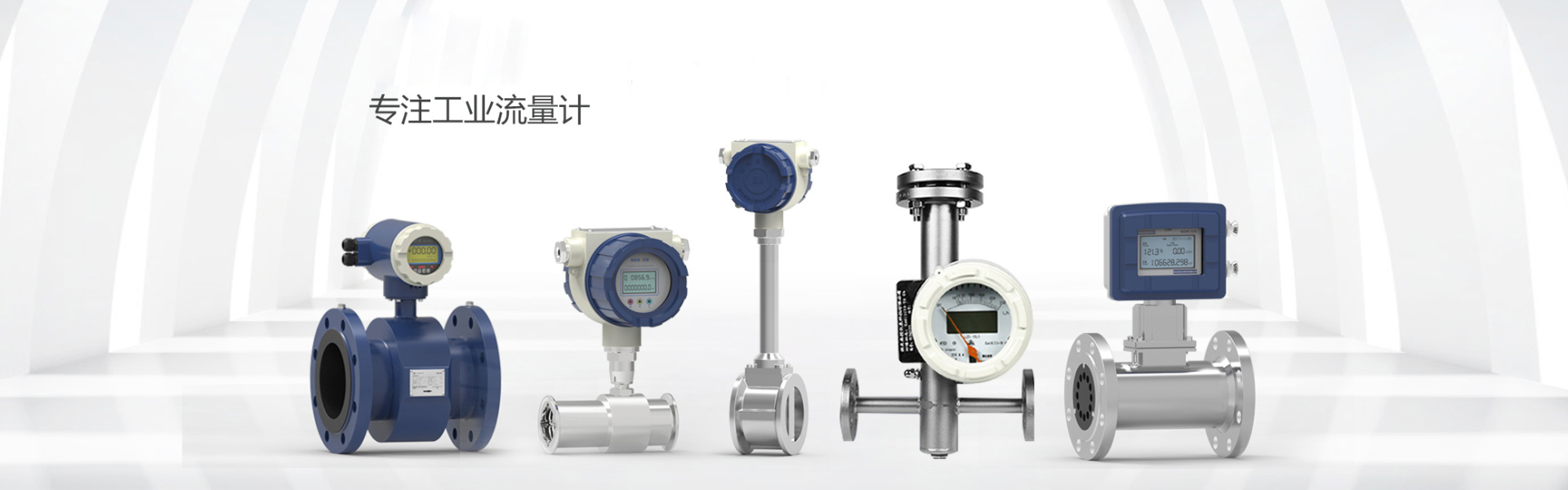
 LDB Integrated Electromagnetic Flow Meter
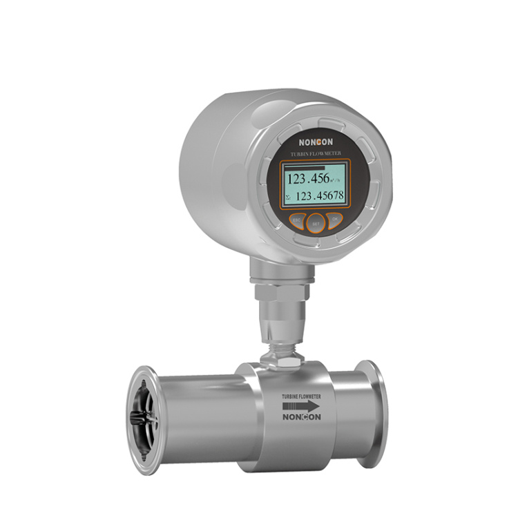 LWGS Food Hygiene Turbine Flow Meter
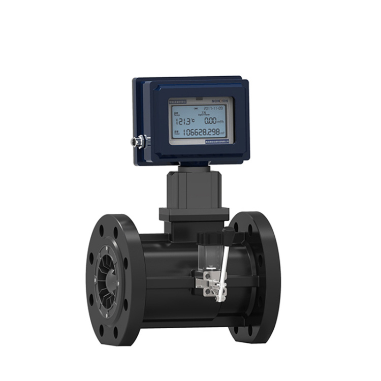 LWGQ Series Gas Turbine Flow Meters
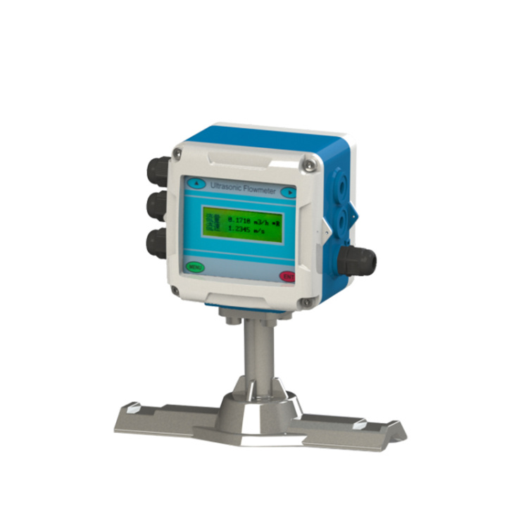 Fixed ultrasonic flowmeter
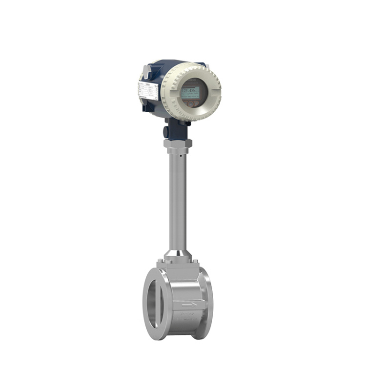
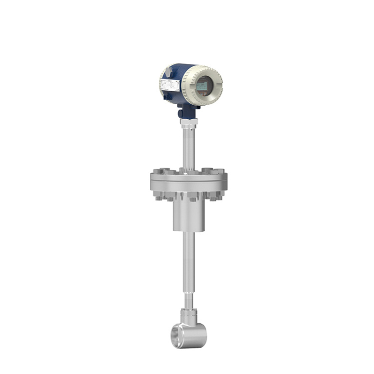 LUGC Insertable Vortex Flow Meter
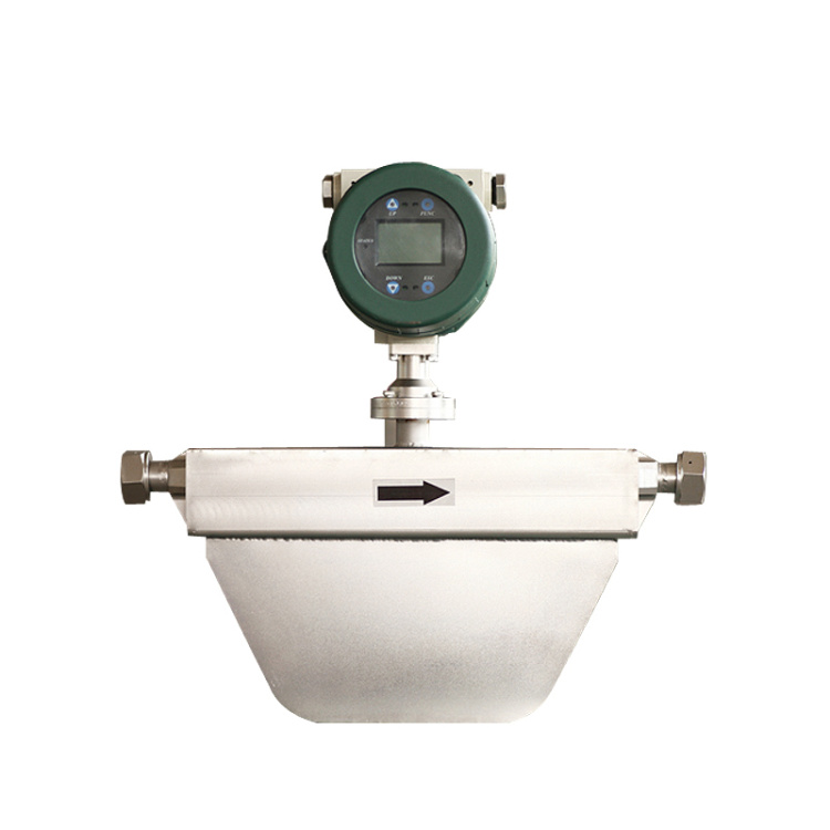 Liquid Mass Flow Meter
 LF Series Liquid Mass Flow Meters
Product Details


产品Price Negotiable
最小起订Quantity: 供货总Quantity:


Do you offer customization? |
|
Specs |
Complete |
Shipment Time |
As per product requirements |
Ⅰ. Product Features Figure 3 - Structural Form
■ No moving parts, long-term stability, simple structure for easy installation and maintenance;
The sensor output is a pulse frequency, which is linearly related to the actual flow rate of the measured fluid, with no zero-point drift and excellent stability. The structural forms are diverse, including pipeline and insertion type flow sensors.
■ High accuracy, typically with a measurement precision of ±1.0% for liquids and ±1.5% for gases.
Wide measurement range, up to 1:20 in the Reynolds number range of 2x10^4 to 7x10^6.
Low pressure loss (about 1/4 to 1/2 of orifice flowmeters), belongs to energy-saving flow meters.
Flexible installation methods; can be horizontally, vertically, and at various angles inclined, depending on the on-site process piping.
■Utilizes anti-interference circuitry and vibration-resistant sensor heads, offering certain environmental vibration resistance.
Utilizing ultra-low power single-chip microcomputer technology, a single 3V10Ah lithium battery can last for over 3 years.
The仪表系数non-linearity is corrected by software, enhancing measurement accuracy.
■ Utilizes EPROM for power failure protection of accumulated flow, with a protection time exceeding 10 years.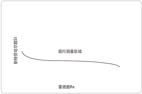
Figure 1: Relationship between Strouhal Number St and Reynolds Number Re
II. Operating Principle
The vortex flow sensor is composed of a vortex generator, a detection probe, and the corresponding signal amplification circuitry.
As fluid flows past a vortex generator, alternating rows of vortices are formed on both sides, known as the Karman vortex street. Based on the Karman vortex street theory, Strouhal proposed that the frequency of the Karman vortex street is proportional to the fluid velocity, and provided the relationship between frequency and velocity: F = St × V/d
Equation: F: Vortex shedding frequency (Hz)
V: Average flow velocity (m/s) on both sides of the vortex generator
St: Strouhal Number (constant within a certain Reynolds number range)
d: Vortex Generator Inflow Surface Width (m)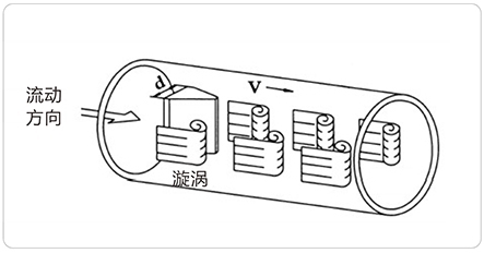
Figure 2: Schematic Diagram of a Vortex Flow Meter Principle
These alternating vortices form a series of alternating fluid lift forces. When these forces act on a piezoelectric effect-based detection probe, they generate a series of alternating charge signals. After being converted, shaped, and amplified by a pre-amplifier, the output is a pulse signal that is in phase with the vortex shedding frequency and proportional to the flow velocity.
Section III: Product Categories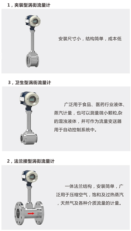
Section IV: Product Selection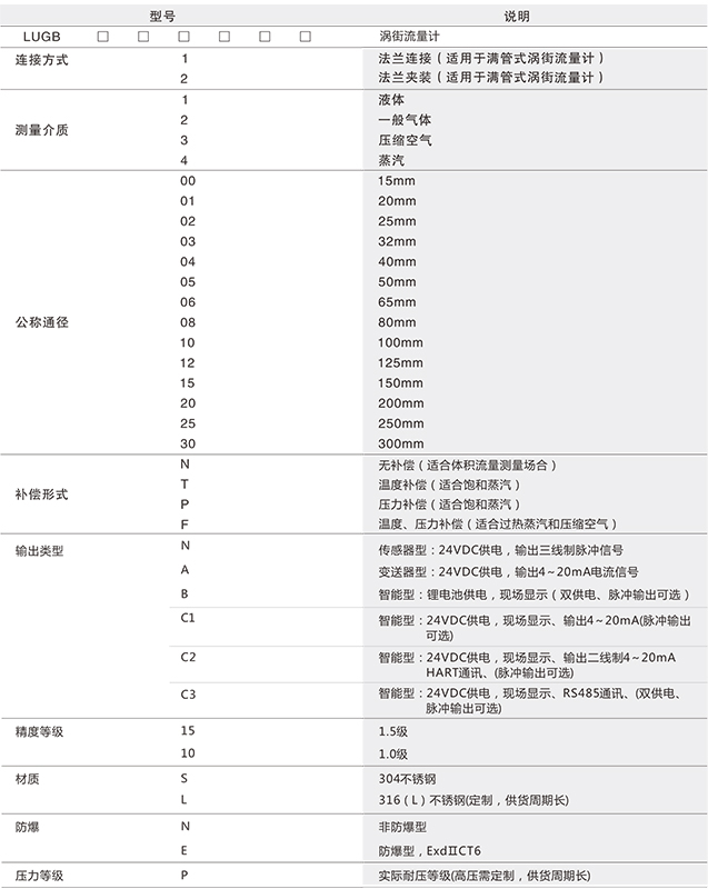
V. Structure and Installation Dimensions
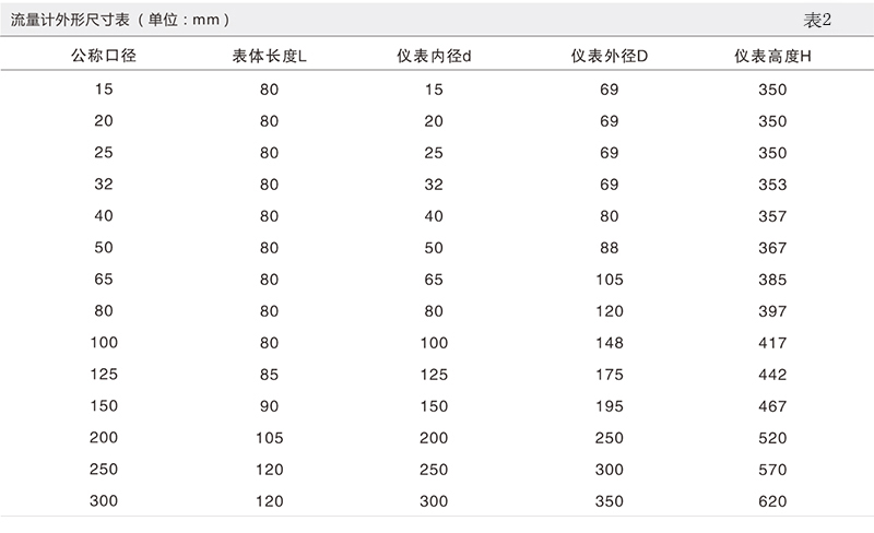
Installation dimensions for the full-bore turbine flow sensor are shown in (Figure 3) and (Table 2).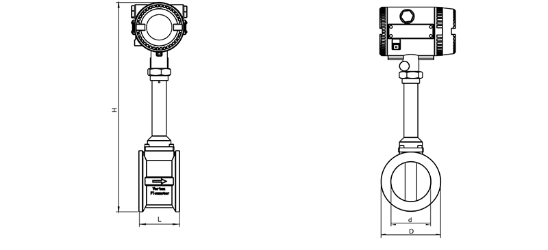
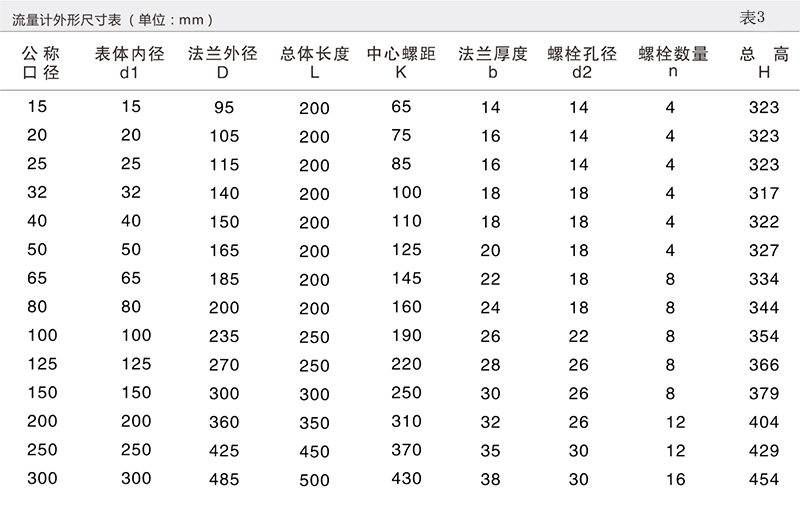
2. The main geometric dimensions of flange-mounted flowmeters are shown in (Figure 4) and (Table 3).
Figure 4 Structural Form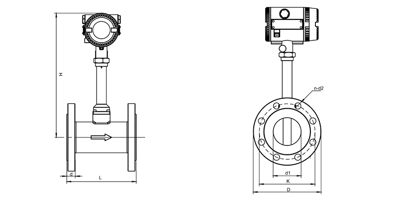
VI. Flow Meters Installation Forms (See Figures 5-9)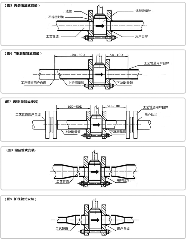

Phone Consultation