Committed to intelligent motor testing equipment and auto...

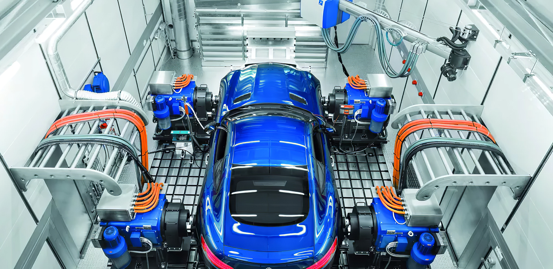
The vehicle undercarriage dynamometer is one of the key testing equipment for automotive chassis, used in automotive engineering for comprehensive condition inspections. Previously, it was predominantly used in new vehicle manufacturing and testing. In the 1980s, the application of dynamometers began to spread in China, and today, the majority of the thousands of vehicle performance testing stations across the country are equipped with this low-cost undercarriage dynamometer.
On the requirements for undercarriage dynamometers used in vehicle testing, there is a demand to ensure certain accuracy and compatibility with various functions while keeping the cost low. However, these dynamometers face numerous issues: such as low accuracy in measurement data; poor reliability due to internal resistance differences caused by different mechanical structures; difficulty in correctly evaluating vehicle power; lack of compatibility with emission testing dynamometers; difficulties in accurately simulating road resistance, and so on. Added to this are factors like low automation and intelligence levels, complex operations, etc., which hinder many testing institutions from fully utilizing and leveraging the dynamometers. In light of these circumstances, addressing key technologies such as data accuracy, functional compatibility, stable and reliable performance, and intelligence, is the task for the application and promotion of undercarriage dynamometers.
After years of effort, through addressing key issues in the use of dynamometers for vehicle undercarriage testing, applying mathematical analysis based on similar principles, optimizing the mechanical structure, improving control methods, and establishing correction models, we have achieved a significant enhancement in the functionality of dynamometers used for vehicle testing, all without increasing manufacturing costs, as verified by extensive testing.
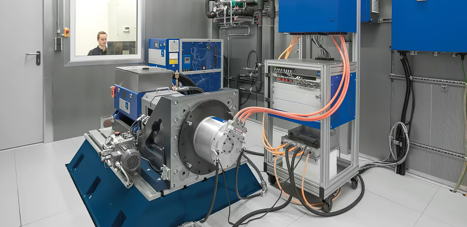
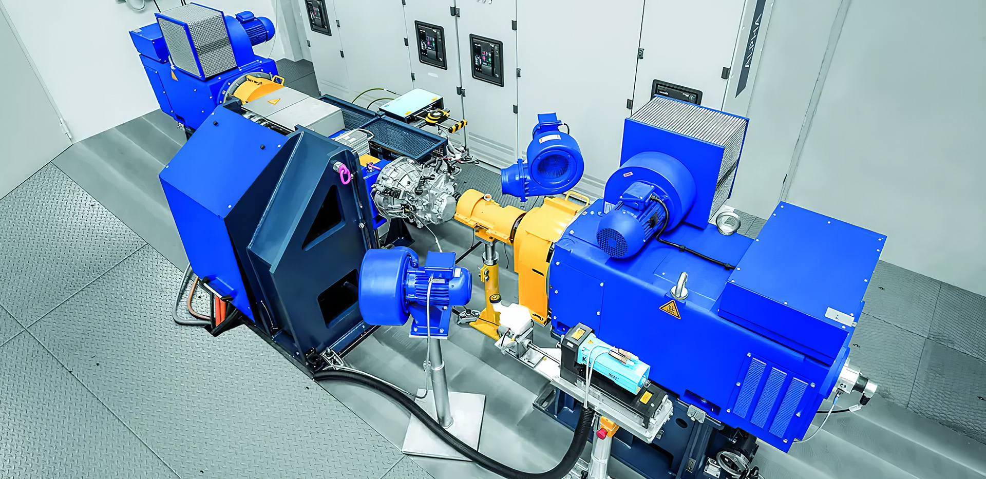
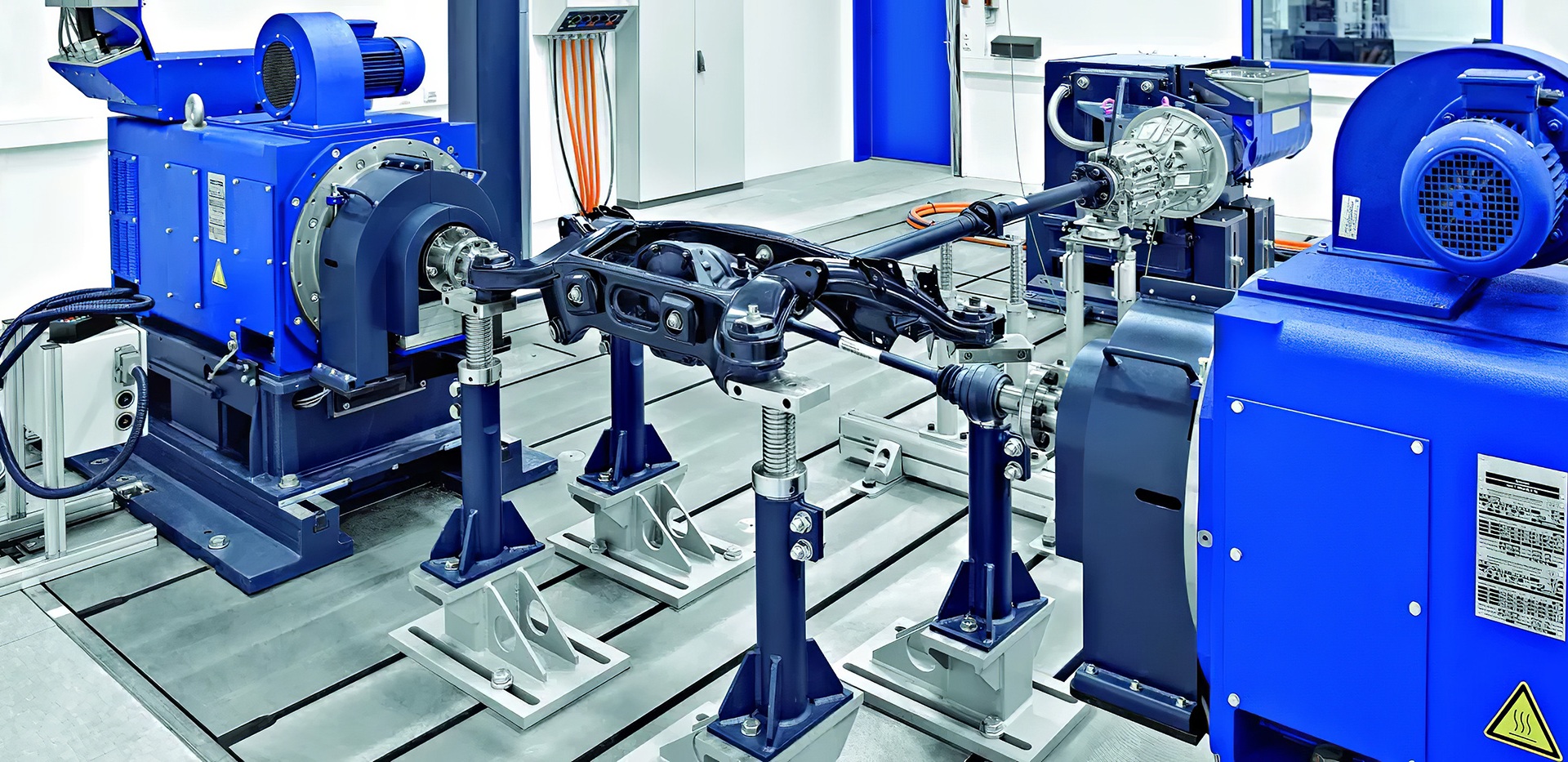
The undercarriage dynamometer frame structure is typically a dual-drum design for vehicle undercarriage dynamometers, with two drums on each side supporting the left and right wheels, forming a four-drum setup. When the left and right wheels of a vehicle are supported on the same shaft, the structure is a two-drum configuration. The rolling resistance of a vehicle on the road is different from that on a dynamometer frame. To simulate the road-running conditions of a vehicle on a test bench, it is first necessary to accurately simulate the vehicle's overall motion inertia and driving resistance. The diameter, spacing, and surface material of the drums are the main structural parameters of the undercarriage dynamometer, and their influence on rolling resistance is mainly reflected in the size of the tire deformation curvature. After many years of practice, most factories use a four-drum arrangement for undercarriage dynamometers, consisting of four short drums with eight support points and at least two shaft couplings. Due to the continuous changes in concentricity caused by assembly quality and frame stress effects, the internal motion resistance remains unstable, which is an important factor causing unstable test data in such undercarriage dynamometers. The dual-drum dynamometer consists of two 2.5 drums, half the number of support bearings, and reduced shaft couplings, resulting in smaller mechanical losses on the frame. In practical applications, it shows significant improvements over the four-drum dynamometer. The actual measured values of internal resistance for the two different drum types show that the dual-drum dynamometer has less internal resistance than the four-drum setup.
After long-term observation, the long-term stability of two-roller systems is significantly better than that of four-roller systems, making them worthy of promotion. For the chassis dynamometer tests on vehicles in use, the sliding correction and acceleration resistance loading control typically use mechanical inertia simulation. Due to the limited number of flywheels and the difference in rolling resistance between the test rig and the road, adjustments must be made to the acceleration, sliding distance, and time measurements obtained from the test rig.
After multiple trials exploring simple, convenient, and precise testing methods, the relationship between the skid distance on the road and the skid distance on the test stand is as follows: The company has reached a consensus on these parameters, such as using a 218mm roller diameter for measuring compact cars; for heavy vehicles, a diameter of 370mm to 420mm is commonly used, with the roller spacing treated differently for small and large vehicles; the application of hard alloy spray on the roller surface to increase roughness has been widely implemented. It is particularly important to note that the internal resistance and relative stability of the dynamometer test stand greatly affect the measurement results, and this needs to be paid close attention to.


b2b.china9.net © Zhongshang 114 Hebei Network Technology Co., Ltd.Address: Room 6009, Oriental New World Center, No.118 East Zhongshan Road, Qiaoxi District, Shijiazhuang City, Hebei ProvincePlatform Service Hotline: 4006299930