


Product Introduction:
The GWB-200JA Extensometer Calibrator is a high-precision displacement micrometer instrument in a pure mechanical design. According to the requirements of the JJG762-92 Extensometer Verification Regulation, it is specifically designed for calibrating various extensometers and is also widely used for verifying displacement sensors, as well as the calibration of corresponding percentage and decimal percentage gauges.
Displacement change reading:
L=(a+0.001b+0.0001c)-(a0+0.001b0+0.001c0)
Among them: a - inner cylinder millimeter scale reading
Outer tube graduation reading
Cursor line reading
a0, b0, c0 are the readings before the corresponding displacement changes.
Instructions for Use:
Please carry out the calibration of extensometers in accordance with the requirements of the JJG762-92 extensometer calibration specification.
1. Select a separation sample that is essentially consistent with the test sample, based on the specifications and model of the extensometer being inspected and the specifications of the test sample.
2. Adjust the position of the two measuring arms to achieve suitable calibration space; adjust the position of the eccentric spring on both measuring arms to ensure the two separated specimens are coaxial; adjust the distance between the micrometer head and the lower base to ensure the effective travel of the micrometer head. After all adjustments are made, tighten all necessary securing areas. During the calibration process, except for the permitted motion displacement, no sliding or loosening is allowed.
3. Extension gauge calibration scope, selection of testing points, and testing procedures:
1) The calibration range should be determined based on the technical parameters of the material to be tested by the extensometer. For instance, if testing σP0.2 technical data of steel specimens with a 50mm gauge extensometer, please select a calibration range of 1mm. If the measurement of n value is required, then a calibration range of 25mm is needed.
2) For the selection of verification points, generally, there should be no fewer than 8 points per range. For the above examples, within the verification range of 1mm, 10 points are verified, which means one point per 0.1mm.
3) Always use the integer scale multiple reading method for extensometer calibration; do not estimate readings with a cursor or decimal place readings, as each ten-point reading has already caused fatigue in the reading process.
Readings can exacerbate measurement errors. Integer single-scale readings offer clear, simple, and accurate readings, with a low probability of error. Even if errors do occur, they are quickly detected, as the error in the multiple reading of integer scales will proportionally increase the extensometer error value. Such gross errors are promptly identified.
4. Use of Extended支柱: When using the basic pillar to calibrate the extensometer, if the distance between the extensometer's gauge spaces cannot be guaranteed, remove the protective cap from the basic pillar, insert the extended pillar into the main pillar and align it with the V-shaped groove, then tighten the screws. Make sure it is securely fastened before use.
Maintenance and care:
1. When disassembling or assembling the upper and lower arm, prevent the positioning pin or steel ball from falling out. Only use a screwdriver to open the clamp if it's too tight.
2. The differential head is pre-calibrated upon the equipment's factory shipment; it must not be disassembled by the user during operation.
3. Use in a clean, dust-free environment and ensure the instrument remains clean and dust-free at all times.
4. Be mindful to prevent damage from external forces and the occurrence of rust.
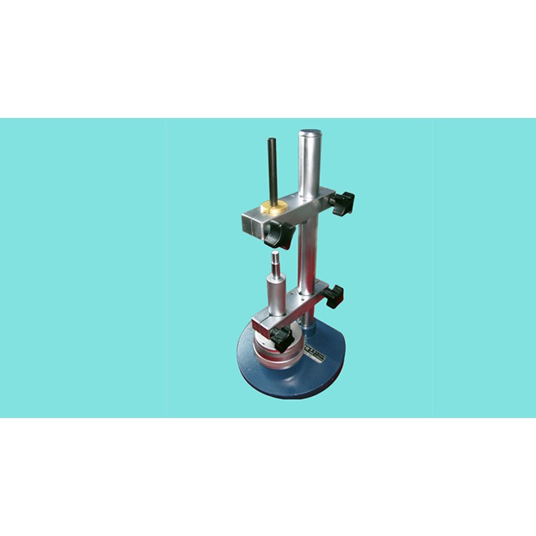
Product Images:
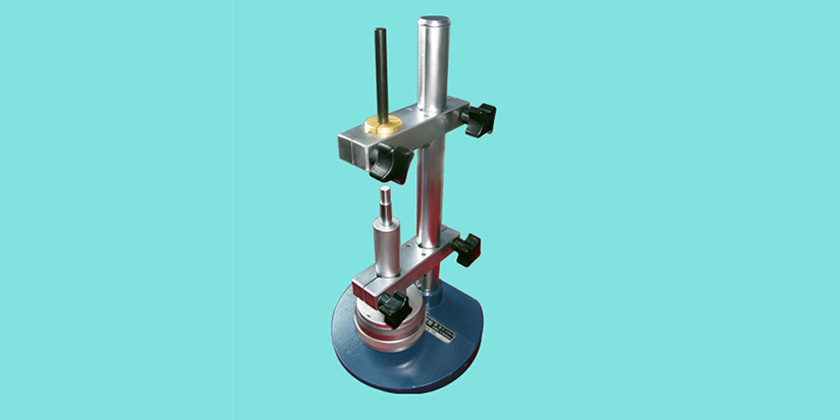
Structural Features and Reading Method:
1. This instrument consists of a precision differential probe and a measuring bracket. The calibrator features a modular design. The precision differential probe and arm can be combined in various ways or positions, and it comes with extended column attachments. It includes separate specimens in various forms such as cylinders, plates, and blades, allowing for easy calibration of extensometers in multiple specifications and models. Users can also customize accessories for precise micro deformation measurement to meet their specific testing needs.
2. The precision differential probe is composed of a sliding rod, a measuring rod sleeve, a reading inner cylinder, a reading outer cylinder, and a high-precision threaded connection. It has a large measuring range of 25mm; a small graduation (vernier graduation) of 0.0002mm; and a rotating outer cylinder graduation of 0.002mm.
The instrument comes with measurement accessories.
2 pieces of combined calibration rods. Used for assembling various simulated separation samples.
2. 4 blades. Mounted on the combined calibration rod: Used for COD or JIC gauge calibration.
3. Two cross-section test pieces. Mounted on the combined calibration rod: for the calibration of the lateral extensometer.
4. Two board pieces. Installed on the assembly calibration rod: used for certifying board sample simulations.
5. φ10×100 rod, 1 piece. Placed in the upper support arm spring hole for calibration of specimens with diameters of 10mm or more.
6. φ10×50 rod, 1 piece. Placed inside the micrometer head adapter for simulating the calibration of specimens with diameters of 10mm or more.
7. φ10/φ5 x 100 reducer rod, 1 pc. Designed to fit into the upper support arm spring hole for simulating the calibration of specimens with diameters less than 5 mm.
8. One φ10/φ5×50 reducer bar. Placed inside the upper support arm spring hole for simulating the calibration of specimens with diameters under 5mm.
9. 1 extended 170mm upright. Used to increase the height of the calibrator.
10. 1 Connector Kit. Place on the φ10 end of the differential probe's sliding rod for connecting and separating specimens during calibration.
11. For easy adjustment and installation, a 14mm socket wrench, a 3mm hex wrench, and a flat-head and Phillips screwdriver are included with the instrument.
Technical precision indicators:
1. Measuring Extensometer Span Range Lmax 500mm
2. Measurement of mounting hole diameter on the support arm of the bracket: φ10; φ28
3. Differential probe reading inner cylinder axial graduation 0.5mm per graduation
4. Differential probe reading inner cylinder vernier scale 0.0002 mm/grad
5. Differential probe reading outer cylinder circumference graduation 0.002mm/grad
6. High-precision differential probe accuracy specification
Calibration Instrument Indication Error:
0.5mm or less ≤ 0.5μm | Absolute Error
Span above 0.5mm ≤ 0.10% Point-to-point relative error
Reference Standard:
JJF 1096-2002 Extensometer Calibrator Calibration Specification
ISO 9513:1999 Calibration of Extensometers for Uniaxial Testing of Metallic Materials
JJG762-1992 Extension Gauge Verification Procedure
Calibration for 0.5-grade extensometer
