


- AllProduct Category
-
Pressure Transmitter
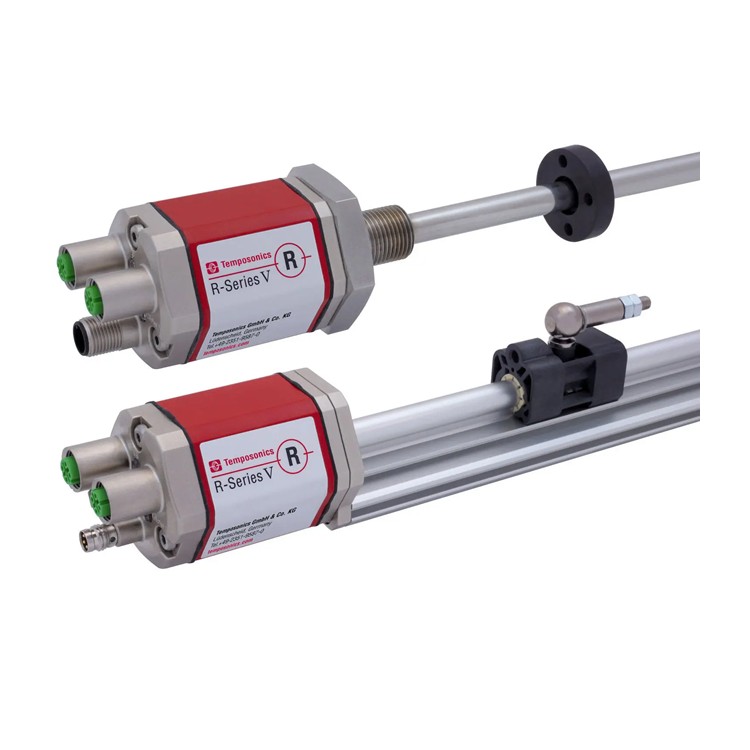
Linear Position Sensor
Tie-rod Position Sensor
Magnetic-Inductive Level Gauge
Magnetic-Induced Eddy Current Displacement Sensor


详情描述
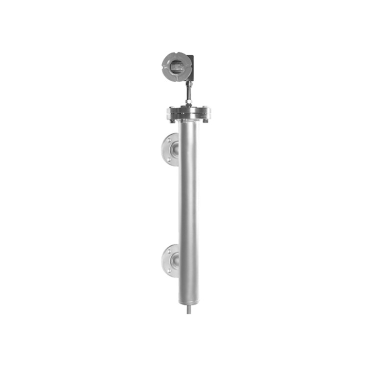
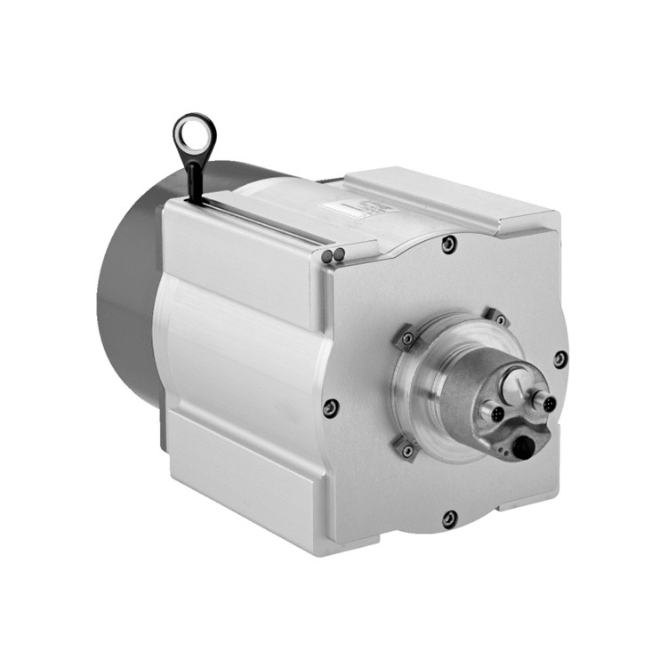
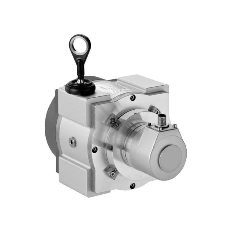
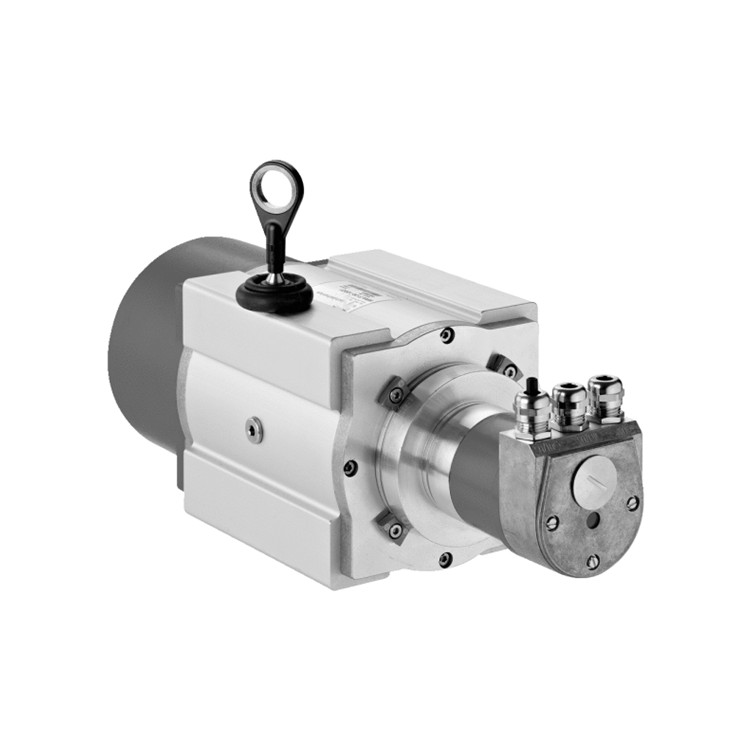
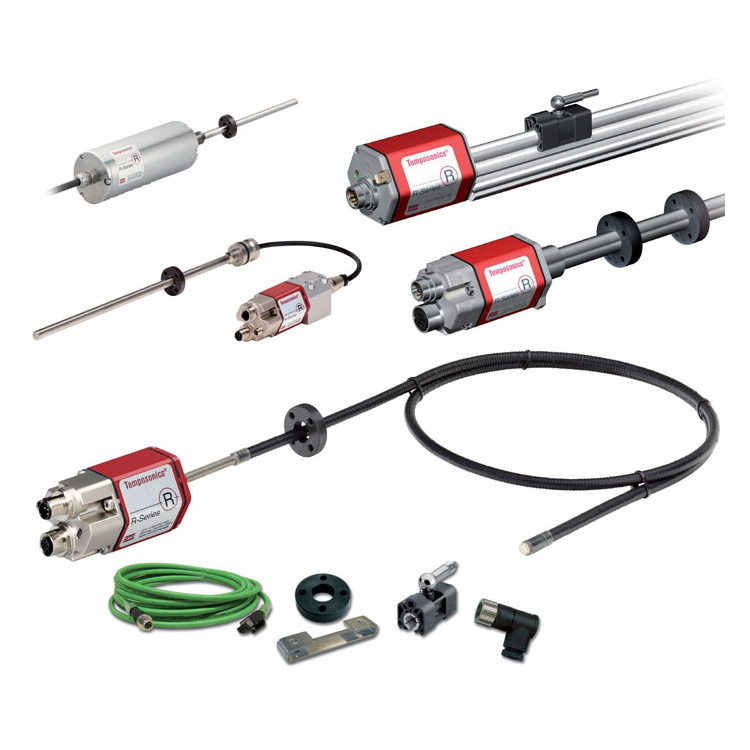
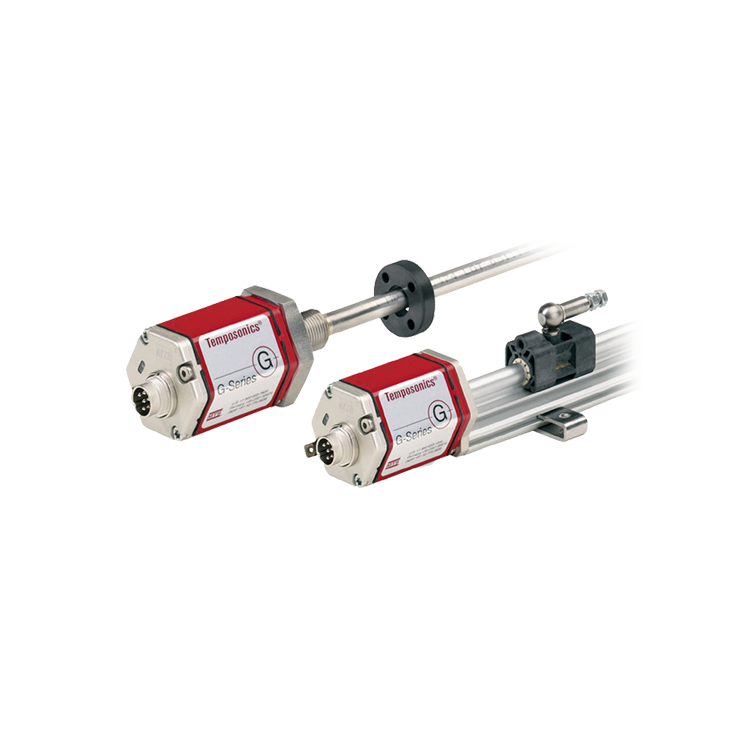
High-precision buoy level gauges are based on the magnetostrictive principle, consisting of a magnetostrictive level gauge and an external floating buoy. They offer various installation options and are powered by a 4~20mA/HART, Modbus, or Profibus output. These gauges can measure both liquid level and interface either individually or simultaneously, effectively avoiding the drawbacks of traditional buoy level gauges, such as high sensitivity to temperature and density changes, physical calibration, metal fatigue in torsion tubes, and extensive maintenance. They also feature typical advantages like high precision, high reliability, and maintenance-free operation.
Technical Specifications:
| Purity | ±1mm or 0.03% of full scale | Supply Voltage | 16~30VDC, with unipolar protection |
| Ambient Temperature | -40~65℃ | Display | LCD |
| Signal Output | Two-wire system, 4~20mA/HART | Intrinsically Safe Rating | Ex ia IIC T4,Ex d IIC T6 |
| Ingress Protection (IP) rating | IP67 | Process Pressure | Vacuum ~16 MPa |
| Process Temperature | 0~149℃ | Range | 0.15~4.5m |
| External Diameter of the probe rod ① | 1/2" or 5/8" | Bottom Dead Center | Less than 2.5" |
| Probe rod type | Rigid rod | Rod material | 316L SS |
| Process connection | Short pipe or flange | Table Header Structure | Single-chamber |
| Shell Material | Die-cast aluminum/stainless steel | Shell Treatment | Polyester coating (for die-cast aluminum only) |
| Electrical Interface | 1/2 NPT(F) or M20×1.5 | Exhaust Emission Removal | Plug/Valve |
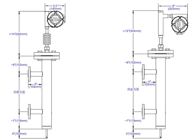
Dimensions and Structure:
Features:
Multi-functional: capable of measuring liquid level and interface individually or simultaneously
High precision: Measurement accuracy up to ±0.38mm or 0.01% of full scale (whichever is greater)
Low-maintenance: Core components do not come into direct contact with the medium, requiring no regular maintenance
No calibration required: Intelligent design with automatic parameter storage, no physical calibration needed
Easy to operate: Standard buttons, no additional auxiliary equipment required
Easy installation: Simple to install, NPT/Flange connection
High safety: Ex ia IIC T4, Ex d IIC T6 explosion-proof rating and IP68 protection rating
Low power consumption: LCD display, two-wire system powered by 4~20mA/HART, Modbus, or Profibus output options available
Application Industry and Equipment:
Boilers: Steam Drum Level
Tank Area: Refineries, Oil Storage Facilities, Gas Stations, Chemical Product Warehouses, Petrochemical Enterprise Storage
Power: auxiliary equipment level (high-pressure, low-pressure, deaerator, condenser, shaft seal heater, etc.), chemical water treatment
Silicon Industry: Organic Silicon, Polysilicon
Petroleum & Petrochemical: Oil and gas exploration and gathering, refining, ethylene, and triol production
Other: Metallurgy, Papermaking, Water Treatment, Biology, Food & Beverage, Light Industry, etc.
Process Installation:
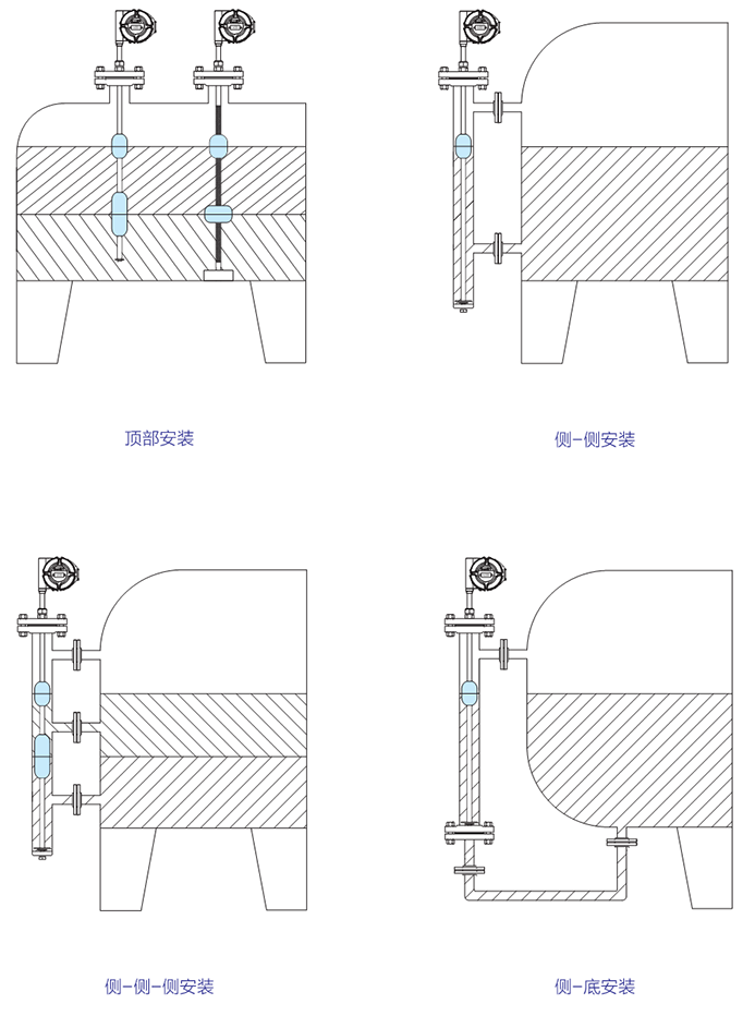
Installation:
Avoid bending or damaging the liquid level probe rod during installation. If the probe rod bends, it will hinder the float from moving freely on the rod, thereby affecting the measurement results. The installation steps are as follows:
1. Verify if the float size can fit smoothly into the buoy tube or mounting hole, as well as ensure that the related accessories are suitable.
2. The float is directly mounted onto the probe rod of the level gauge and can move freely along it. When installing the float, ensure that the direction marked with "UP↑" aligns with the measurement direction.
3. Clean the probe rod and buoy of the level gauge, removing any attachments and stains.
4. Ensure the "0" point is aligned during installation. If the ordered product requires a fixed flange, install it directly at the site; if the ordered product does not require a fixed flange, align the "0" point during site installation. When the level gauge shows the liquid level as 0mm, secure the level gauge to the installation flange.
5. Clean off any adherents and stains that may accumulate during the surface installation of the level gauge.


